F-TPMS Fermentation Monitoring Part 1

About 2 months ago I saw Andreas Speiss talking about using TPMS sensors for monitoring his bottle carbonation. He was having to fabricate a cap that could accomodate the sensor. It got me thinking. Why can’t I just use the outboard sensor types with a valve stem and call it day?

So I decided to add some off the shelf EXTERNAL type TPMS sensors to my brewing kegs. I call it Fermentation Temperature Pressure Monitoring System or FTPMS. Yes…I like acronyms.

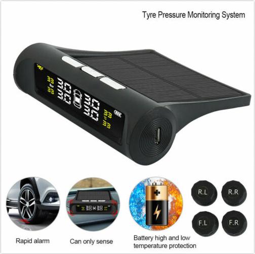
Some background if you require it….A TPMS (Tyre Pressure Monitoring System) uses wireless temperature and pressure sensors on each valve stem to monitor and warn of out of bounds conditions namely over/under-pressure, over-temperature. They report back to a central controller with a display for temperature and pressure.

These measurements are highly useful in pressure fermentation or Grünschlauchen, not so much plastic fermenter type setup…

I bought the set of four because you get the display and receiver unit which I will hack in Part 2 to allow you to run more than 4 sensors.

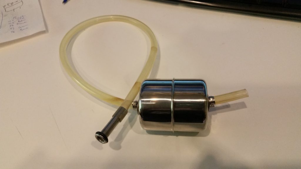
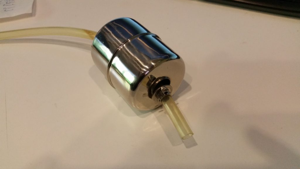
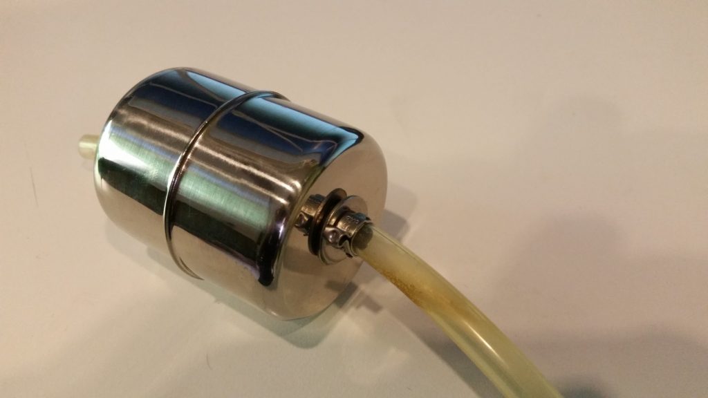
I used an off the shelf tyre valve stem that was designed to fit to high quality alloy wheels rather than the push in rubber type.

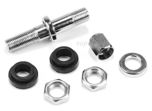
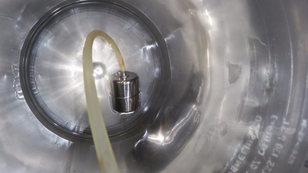
These are made out of stainless steel. All you have to do is drill a 8mm diameter hole in the top of the keg lid and then fit this valve assembly.

Installation

I used a 90 degree brass motorcycle valve stem for mine. Similar to the one below:

The Schrader thread was a bit shite so I had to clean it up for the TPMS sensor to fit nicely. My advice is to use the stainless steel stem shown in this post.

The Result

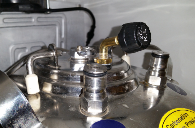
Thats the Rear Left sensor fitted to Fermentation Keg 1. I have two fermentation kegs so I used R.L and R.R.

On the screen it is showing the telemetry:

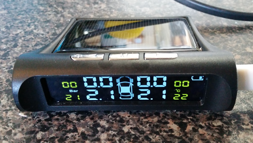
As you can see the screen reports back the temperatures in C and the pressures in Bar.

Parts Required

You can convert up to 4 kegs with 1 kit.

4 sensor TPMS EXTERNAL SENSORS with Receiver

4X schrader valve stems

In part 2, I will be finding a way to run more than 4 sensors using a custom made Arduino based 433MHz receiver….

I2C/IIC longer cable runs without extenders

Recently I was building some custom boards which had an 0.96″ OLED display that was remotely mounted. In my prototyping I noticed no ill effects from extending the 4 core cable to the OLED display.

The wiring comprised of GND, 3.3V, SCL and SDA signals. I had 4.7K pullups at the board side.

Then came the issue when I had replicate across the production units with the cables at 2.2m each.

I was perplexed since I had a working example at 2m.

The only difference was the prototype used 4 core screened audio cable (individual screens) vs the production version of single screened UTP.

Turns out, CAT6 is a poor choice for I2C even at lengths of a metre or so. Even with the following configuration:

  • SDA on Orange
  • GND on Orange/White
  • SCL on Brown
  • GND on Brown/White
  • 3.3V on Green
  • GND on Green/White
  • 3.3V on Blue
  • GND on Blue/White

I tried varying the clock speed from 700KHz to 400KHz to 100KHz to 10KHz  and even 100Hz…no such luck.

I even tried adding a separate 3.3V power supply and additional pull ups at the OLED panel. No luck.

Turns out the solution was under my nose all along. The 4 core screened audio cable. Specifically from Jaycar, WB-1510, works flawlessly at lengths up to 3m (that I have tested). It could work with even longer lengths! Just make sure you ground all the screens at the board end to earth/chassis.

Hope this helps someone out there that is having issues with I2C beyond a metre….

DIY Keg Floating Dip Tube Mk2

Move over Mk1

In Mk1 version, there was a filter. I got feedback that this was causing grief when it got blocked. Additionally the build cost was on par with the off the shelf Fermzilla float. Well, we can’t have a situation where DIY cost more in parts than the commercially available item!

Mk2 Simpler Float

Mk2 works as follows

  1. The same float from Mk1
  2. The same replacement gas diptube OR cut down your existing liquid diptube
  3. The same length of silicone tubing as Mk1
  4. Except now, the float is held in place by two 316L 8mm flat washers, held in place by 2 Oetiker clamps.
  5. Note, the Oetiker clamps are push fit on this 8mm tube since they are 7mm. DO NOT CRIMP the clamps as you will not be able to dismantle and clean the float.

Notice that the float has an indentation/dimple in the side that is HEAVIER. You need to face this side to the bottom. If your float doesn’t have an indentation, you can find the heavier side by placing the bare float in a jug of water.

This is the bottom side of the float. Leave about an inch of tube overhang.

This the top side of the float. Don’t make the fit tight as you want the float to rotate freely on the tubing. Again DO NOT CRIMP the Oetiker clamps.  In the photos it is apparent that I did clamp mine because they were oversized. I used 9.5mm Oetikers for the prototype as that is what I had on hand).

As you can see below, the float  sits with the diptube under the water level.

You can fine-tune the float by adding more washers to the bottom side if your float does not behave properly.

Parts Required

Stainless Steel Float http://ali.pub/229u9j

Food grade Silicone Tube 10mm OD 7mm ID http://ali.pub/229umy

8mm Keg Diptube Short/Gas http://ali.pub/229vui

316L Washers (need 2) http://ali.pub/3ru9v6

7-9mm Oetiker Clamps (need 2) http://ali.pub/3ru9r3

Note, the clamps are not crimped. The only reason you would crimp them slightly is to get a tight (interference) fit on the silicone tube. This will allow you to adjust / fine tune and more importantly clean your diptube float assembly.

The list above will probably contain more parts than you need to make one float. ..

Feedback

I would appreciate some feedback on this new design if you decide to build mk2…

UPDATE 18.10

Mk3 is ready and working better than ever and way cheaper!

http://think.gusius.com/diy-keg-floating-dip-tube-mk3/