A while back I had some issues with my solar array where a string would throw a ground fault on the inverter. It turned out Trina had made a faulty batch of panels where water would leak into the side of the frame. When it rained, the inverter would detect a ground fault.
So I built a calculator that lets me quickly identify one or more panels that are leaking.
String details
Calculated values
Vocp per panel—
V1 ÷ Vocp—
V2 ÷ Vocp—
V1 + V2—
Fault location
String map — positive end (left) to negative end (right)
Exploring Probiotic Species for SIBO and Heart Health
Over the past few months, I’ve been diving deep into the science of probiotics and their potential to support gut health, particularly for conditions like SIBO (Small Intestinal Bacterial Overgrowth) and cardiovascular disease. My focus has been on specific bacterial strains that have shown promising effects on both gut microbiota balance and metabolic health.
Dr. William Davis’ Perspective
Dr. William Davis, author of Wheat Belly and Undoctored, has long advocated for using specific probiotic species to restore gut health. In his research and clinical experience, he emphasizes the role of Lactobacillus reuteri in particular, which he incorporates into homemade yogurts. Davis believes that high-count, strain-specific probiotics can help modulate inflammation, improve immune function, and even support cardiovascular health. His approach focuses less on “perfectly set yogurt” and more on ensuring sufficient bacterial counts for therapeutic benefit—a concept that aligns with modern microbiome research.
In Wheat Belly, Davis highlights the negative effects of processed grains and sugar on gut microbiota and heart health, while Undoctored expands on personalized strategies for reversing chronic disease, including gut-targeted therapies like probiotic supplementation. His yogurt recipes are designed to deliver high concentrations of beneficial strains such as L. reuteri for daily therapeutic use.
My Research & Experimentation
Inspired by Dr. Davis, I began experimenting with L. reuteri, L. gasseri, and even Bacillus subtilis in various dairy media. My goal was to create a reliable method to cultivate these probiotics at home while maximizing their survival and potency. Throughout the process, I experimented with different milk types, cream ratios, and prebiotics like inulin, while closely monitoring pH and fermentation times. One clear takeaway was that traditional visual cues for yogurt texture were less important than ensuring adequate bacterial growth for therapeutic purposes.
Introducing the Fermented Dairy Composition & CFU Estimator
To help others replicate and optimize these probiotic-rich yogurts at home, I developed a Fermented Dairy Composition & CFU Estimator. This tool allows you to enter different amounts of whole milk, evaporated milk, cream, and milk powder, then calculates the fat, protein, and sugar content of your mixture. It also gives visual feedback if your composition falls within the optimal range for probiotic growth and palatability.
The calculator makes it easy to experiment safely with your yogurt base while ensuring that your final mix supports the growth of the strains you’re targeting. This tool is particularly useful for anyone following Dr. Davis’ protocols and aiming to produce therapeutic yogurts at home.
Fermented Dairy Composition & CFU Estimator
Fermented Dairy Composition & CFU Estimator Version 1.9
This calculator helps you design a fermented dairy batch with the right fat, protein, and sugar levels to support probiotic bacteria growth — and then estimates how many colony-forming units (CFU) you’ll end up with after fermentation.
It was built with Australian home fermenters in mind. Unlike the US, Australia doesn’t have “half and half” — that familiar American product that sits halfway between milk and cream. Many probiotic yogurt recipes (particularly those following the L. Reuteri protocol popularised by Dr. William Davis) call for half and half as the base. Since we can’t buy it off the shelf here, the calculator lets you combine whole milk, cream, evaporated milk, and other ingredients to hit the same macro targets yourself.
The Two Sections
🧪 Growth Medium Composition
This is where you enter your ingredients. Each ingredient can be toggled on or off with its checkbox. When checked, you can enter the volume (in mL or grams for powder) and adjust the fat, protein, and sugar values to match the specific product you’re using — since these vary between brands.
Available ingredients:
Whole Milk
Evaporated Milk
Pouring Cream
Whole Milk Powder
Water
Prebiotic Fibre (Inulin or Potato Starch)
🧫 Fermentation Parameters
This is where you configure your bacteria strain, starting CFU, incubation time, and temperature. The calculator uses a logistic growth model — meaning growth accelerates early then slows as it approaches the carrying capacity of the medium, which is more realistic than simple exponential growth.
Target Ranges
After hitting Calculate, the composition results are colour coded:
🟢 Green — within the optimal range
🟡 Yellow — below optimal
🟠 Orange — above optimal
The targets used are:
Macro
Optimal Range
Fat
9–12%
Protein
3.5–5%
Sugar
4–6%
These ranges are aimed at providing a rich substrate for probiotic bacteria while keeping sugar low enough to avoid feeding unwanted organisms.
Worked Examples
Example 1 — The Classic L. Reuteri Yogurt (Australian Style)
L. Reuteri is the most popular strain for home fermented yogurt, largely due to the work of Dr. William Davis whose protocol calls for a long 36-hour fermentation at body temperature to achieve very high CFU counts. His recipes typically use half and half as the base — which simply isn’t available in Australia.
The good news is that combining whole milk and pouring cream gets you right into the same fat range. Here’s a straightforward 1 litre batch:
Ingredient
Amount
Whole Milk
700 mL
Pouring Cream (35% fat)
300 mL
Fermentation settings:
Strain: L. Reuteri
Starting CFU: 10 billion
Time: 36 hours
Temperature: 37°C (use the Use Optimal button)
Result: ~11.5% fat, ~3.4% protein, ~3.9% sugar — sitting right in the optimal zone. L. Reuteri thrives in high-fat dairy and the 36-hour fermentation gives it plenty of time to reach a very high final CFU count.
Example 2 — L. Reuteri Large Batch with Evaporated Milk
For a thicker, more set yogurt with better body, adding evaporated milk boosts the protein without dramatically changing the fat profile. This is a great approach if you find the basic milk and cream version too thin.
Ingredient
Amount
Whole Milk
2000 mL
Evaporated Milk
384 mL
Pouring Cream
600 mL
Fermentation settings:
Strain: L. Reuteri
Starting CFU: 10 billion
Time: 36 hours
Temperature: 37°C
Result: Fat lands around 10.8%, protein around 4.1%, sugar around 4.8% — all green. The higher protein content from the evaporated milk gives the yogurt a noticeably better texture while keeping everything in the optimal fermentation range. This is roughly the default batch the calculator opens with.
Example 3 — L. Casei Shirota Using Yakult® as Your Starter
L. Casei Shirota is the probiotic strain found in Yakult®, the small red-topped bottles available at Woolworths and Coles. Rather than sourcing a commercial starter powder, you can use a bottle of Yakult directly as your inoculant — it contains billions of live L. Casei Shirota cells and works very well as a starter culture, making it one of the most accessible and affordable ways to get started.
One 65 mL bottle of Yakult contains approximately 6.5 billion CFU, so use that as your starting CFU value in the calculator.
Ingredient
Amount
Whole Milk
1500 mL
Evaporated Milk
375 mL
Pouring Cream
300 mL
Fermentation settings:
Strain: L. Casei Shirota
Starting CFU: 6.5 billion (one bottle of Yakult)
Time: 36 hours
Temperature: 37°C (use the Use Optimal button)
Result: L. Casei Shirota is a good sugar utiliser and handles dairy very well. After 36 hours you’ll end up with a mild, slightly tangy yogurt with a very high CFU count — at a fraction of the cost of commercial probiotic supplements.
Note that Yakult itself is quite high in sugar (about 11g per bottle), but this is actually a non-issue for two reasons. First, you’re diluting it across roughly 2 litres of dairy so the contribution to the starting sugar percentage is minimal. More importantly, L. Casei Shirota is a strong sugar fermenter — it will actively consume the sugars in the medium (including whatever came from the Yakult bottle) and convert them into lactic acid over the course of fermentation. By the time your 36 hours are up, the finished yogurt will have a significantly lower sugar content than the raw starting mix. The calculator shows the composition of the medium going in, not what comes out the other end.
Example 4 — B. Longum with Inulin for Prebiotic Support
B. Longum is a slower-growing strain but it is exceptionally good at fermenting prebiotic fibres — particularly inulin. Adding inulin to a B. Longum batch provides a significant substrate boost and supports the broader gut microbiome through short-chain fatty acid production during fermentation.
Ingredient
Amount
Whole Milk
2000 mL
Evaporated Milk
384 mL
Pouring Cream
600 mL
Inulin
30 g
Fermentation settings:
Strain: B. Longum
Starting CFU: 10 billion
Time: 36 hours
Temperature: 37°C (use the Use Optimal button)
Result: The inulin provides a 1.30× substrate boost for B. Longum — the largest fibre boost of any strain in the calculator. Despite being a slower divider, the extended fermentation time and the prebiotic advantage mean B. Longum still produces a high-CFU end product. Try comparing the result with and without inulin by toggling the amount between 0 and 30g to see the difference.
Tips
Use the “Use Optimal” button. Each bacteria strain has a different ideal temperature — L. Bulgaricus and S. Thermophilus prefer 42°C, while most Lactobacillus strains prefer 37°C. Clicking Use Optimal fills in the right temperature automatically. You can still override it manually if your incubator runs slightly warm or cool.
The recommended temperature is shown next to the label. Even before clicking the button, you’ll see the strain’s optimal temp displayed in green next to the Temperature field — handy as a quick reference.
Adjust the macro values to match your actual product. The default values are reasonable averages, but full-cream milk from Pauls vs. a home-brand can differ noticeably in fat content. Check the nutrition panel on your carton and update the fields accordingly for a more accurate result.
Prebiotic fibre only boosts CFU if you enter an amount. Selecting Inulin or Potato Starch from the dropdown reveals an amount field. If you leave it at zero, no boost is applied. Different strains respond differently — B. Longum gets the biggest lift from inulin (1.30×), while L. Gasseri also responds well (1.20×).
The CFU estimate is a model, not a lab result. It uses established growth parameters and a logistic growth curve, but real-world results will vary based on starter culture viability, actual incubator temperature consistency, and individual batch conditions. Use the numbers as a guide for comparing recipes and strains rather than as absolute values.
Understanding the CFU Results
After calculating, the fermentation results show:
Starting CFU — your inoculation amount
After X hrs — estimated total CFU at the end of incubation
Final CFU / mL — how concentrated the culture is
Doublings achieved — how many times the population doubled
CFU per 125 mL serving — a practical per-serve estimate
Temperature efficiency — how close your set temperature is to the strain’s optimal, expressed as a percentage
If your temperature is outside the viable range for the selected strain, the calculator will warn you and return zero growth.
Just a short post to cover how to measure voltages below 100mV. I recently was trying to use a HP Common Slot PSU to drive a electrolysing unit. Instead of using my own shunt I decided to use Pin 34 IMONITOR to measure the current output.
What i found was that for currents under 5A, I was getting no reading on the ADC. That is because at 11db Attenuation at 12bits, the minimum measurable voltage is 0.1V or 100mV.
Instead of going down the path of using op-amps. I decided to modify my prototype pcb by changing the tradiional voltage divider input into the following.
Datasheets say (from Murata) that the IMONITOR pin puts out 60.15mV/Amp. For the 60.15mV/Amp the swing would be 0 to 3.9V.
So for 10mV of input the ADC would read 1.216V which is well within the linear range of the ADC. At 12bit resolution thats easily doable.
I found with my 750W HP supply, it was 30.15mV/Amp. So for this 62.5A supply, this would mean a swing from 0V to 1.88V.
The ADC would see 1.101V for 10mV of input.
Note that the leftmost resistor can be adjusted to allow a wide range of inputs offset against the 10K/10K/5V divider.
In Mk2 version, the float was signficantly simplified however setting it up was difficult and I started to move away from the idea of using Oetiker clamps inside the keg (is it safe?)
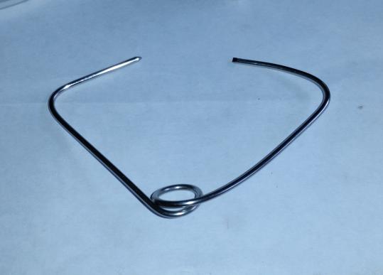
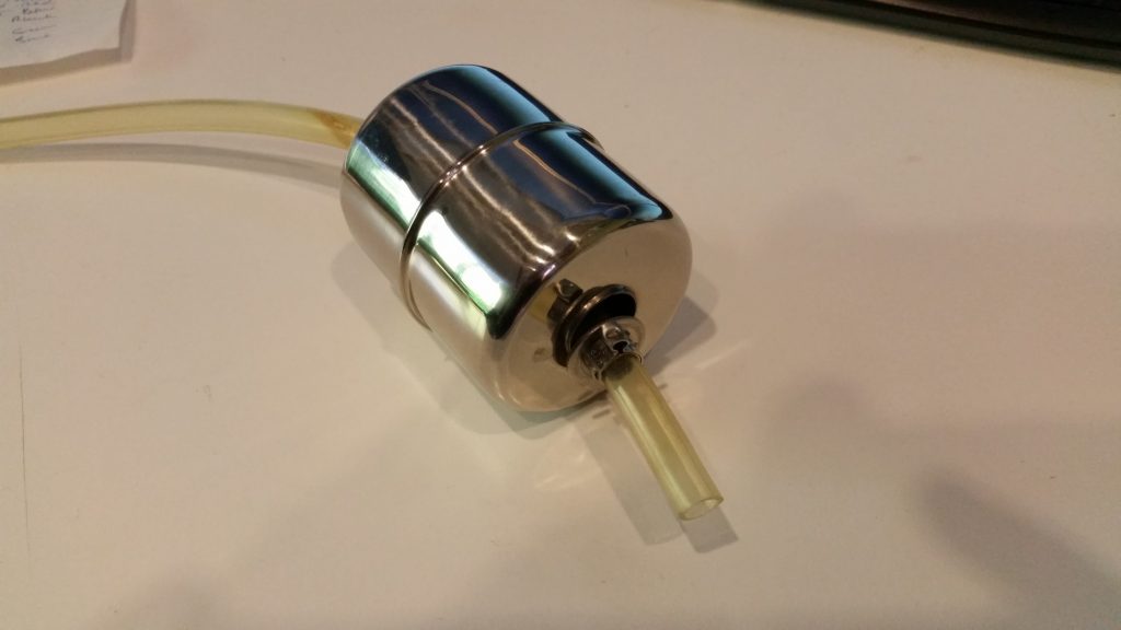
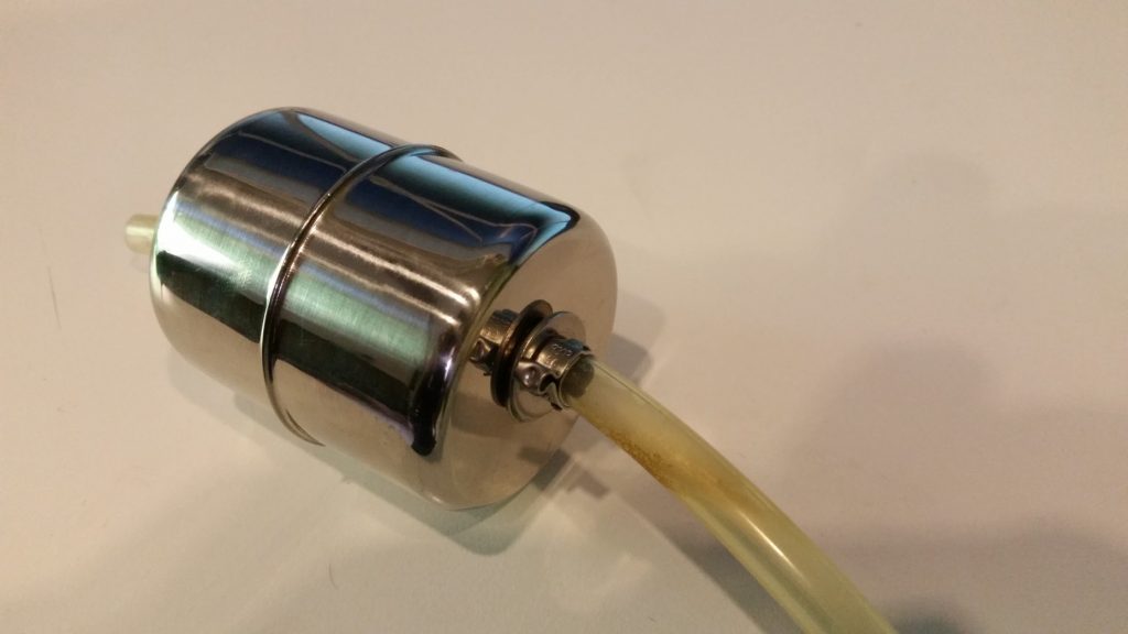
MK3 would have to be the simplest design yet!
Mk3 Simple Float
Mk3 works as follows
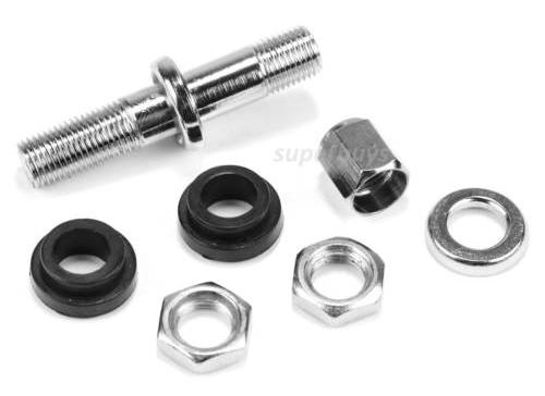
The same float from Mk1 & Mk2
The same replacement gas diptube OR cut down your existing liquid diptube. However now you need another piece for the end of hose
The same length of silicone tubing as Mk1 & Mk2 60cm
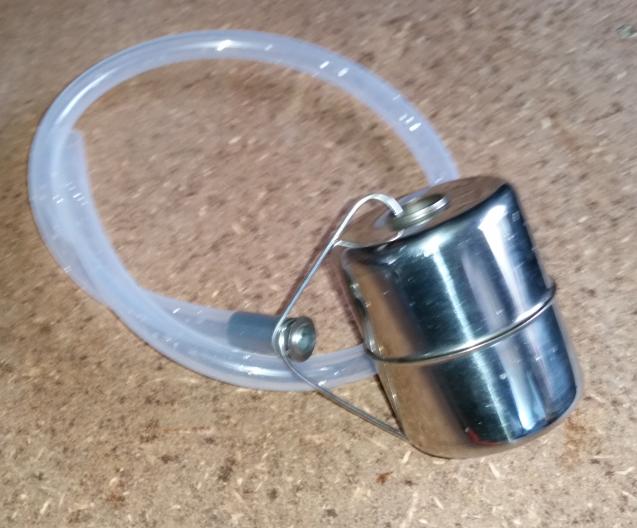
A length of 316L TIG 1.6mm wire is bent to capture the flared end of the diptube and is anchored freely onto the float!
Now the float has an indentation/dimple in the side that is HEAVIER is pretty much irrelevant! You dont needs washers clamps etc. Just some hose, a float and some wire!
The list above will probably contain more parts than you need to make one float. ..
UPDATE: I published this a long time ago. If you want a turnkey solution you can use this. Its a stainless steel ball with the hose and diptube as a kit.
About 2 months ago I saw Andreas Speiss talking about using TPMS sensors for monitoring his bottle carbonation. He was having to fabricate a cap that could accomodate the sensor. It got me thinking. Why can’t I just use the outboard sensor types with a valve stem and call it day?
So I decided to add some off the shelf EXTERNAL type TPMS sensors to my brewing kegs. I call it Fermentation Temperature Pressure Monitoring System or FTPMS. Yes…I like acronyms.
Some background if you require it….A TPMS (Tyre Pressure Monitoring System) uses wireless temperature and pressure sensors on each valve stem to monitor and warn of out of bounds conditions namely over/under-pressure, over-temperature. They report back to a central controller with a display for temperature and pressure.
These measurements are highly useful in pressure fermentation or Grünschlauchen, not so much plastic fermenter type setup…
I bought the set of four because you get the display and receiver unit which I will hack in Part 2 to allow you to run more than 4 sensors.
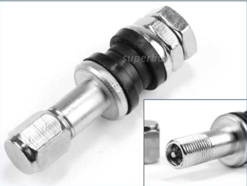
I used an off the shelf tyre valve stem that was designed to fit to high quality alloy wheels rather than the push in rubber type.
These are made out of stainless steel. All you have to do is drill a 8mm diameter hole in the top of the keg lid and then fit this valve assembly.
Installation
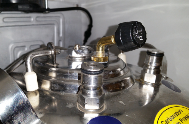
I used a 90 degree brass motorcycle valve stem for mine. Similar to the one below:
The Schrader thread was a bit shite so I had to clean it up for the TPMS sensor to fit nicely. My advice is to use the stainless steel stem shown in this post.
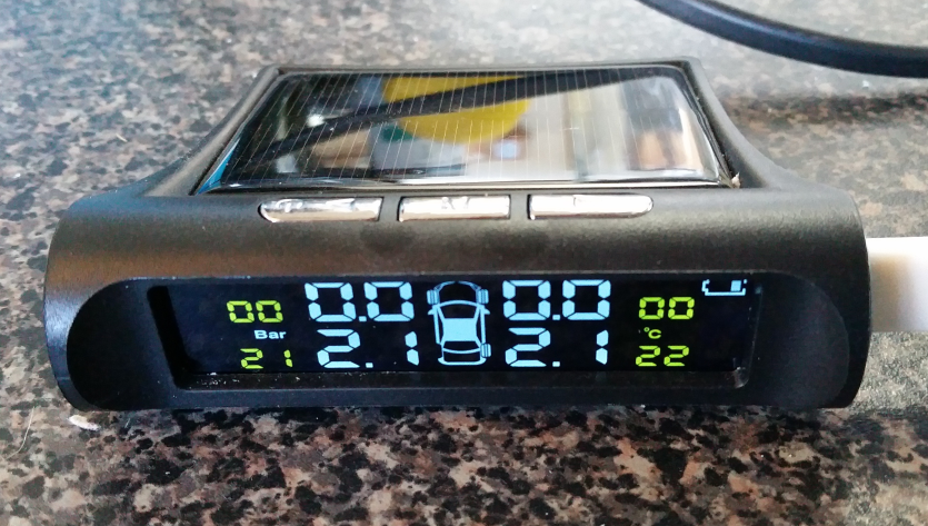
The Result
Thats the Rear Left sensor fitted to Fermentation Keg 1. I have two fermentation kegs so I used R.L and R.R.
On the screen it is showing the telemetry:
As you can see the screen reports back the temperatures in C and the pressures in Bar.
Recently I was building some custom boards which had an 0.96″ OLED display that was remotely mounted. In my prototyping I noticed no ill effects from extending the 4 core cable to the OLED display.
The wiring comprised of GND, 3.3V, SCL and SDA signals. I had 4.7K pullups at the board side.
Then came the issue when I had replicate across the production units with the cables at 2.2m each.
I was perplexed since I had a working example at 2m.
The only difference was the prototype used 4 core screened audio cable (individual screens) vs the production version of single screened UTP.
Turns out, CAT6 is a poor choice for I2C even at lengths of a metre or so. Even with the following configuration:
SDA on Orange
GND on Orange/White
SCL on Brown
GND on Brown/White
3.3V on Green
GND on Green/White
3.3V on Blue
GND on Blue/White
I tried varying the clock speed from 700KHz to 400KHz to 100KHz to 10KHz and even 100Hz…no such luck.
I even tried adding a separate 3.3V power supply and additional pull ups at the OLED panel. No luck.
Turns out the solution was under my nose all along. The 4 core screened audio cable. Specifically from Jaycar, WB-1510, works flawlessly at lengths up to 3m (that I have tested). It could work with even longer lengths! Just make sure you ground all the screens at the board end to earth/chassis.
Hope this helps someone out there that is having issues with I2C beyond a metre….
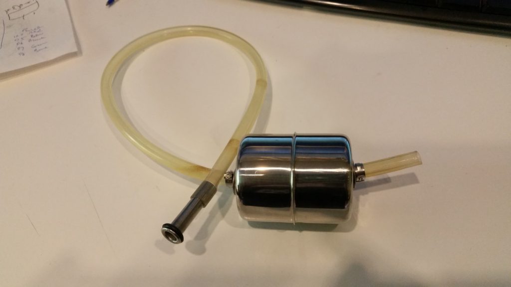
In Mk1 version, there was a filter. I got feedback that this was causing grief when it got blocked. Additionally the build cost was on par with the off the shelf Fermzilla float. Well, we can’t have a situation where DIY cost more in parts than the commercially available item!
Mk2 Simpler Float
Mk2 works as follows
The same float from Mk1
The same replacement gas diptube OR cut down your existing liquid diptube
The same length of silicone tubing as Mk1
Except now, the float is held in place by two 316L 8mm flat washers, held in place by 2 Oetiker clamps.
Note, the Oetiker clamps are push fit on this 8mm tube since they are 7mm. DO NOT CRIMP the clamps as you will not be able to dismantle and clean the float.
Notice that the float has an indentation/dimple in the side that is HEAVIER. You need to face this side to the bottom. If your float doesn’t have an indentation, you can find the heavier side by placing the bare float in a jug of water.
This is the bottom side of the float. Leave about an inch of tube overhang.
This the top side of the float. Don’t make the fit tight as you want the float to rotate freely on the tubing. Again DO NOT CRIMP the Oetiker clamps. In the photos it is apparent that I did clamp mine because they were oversized. I used 9.5mm Oetikers for the prototype as that is what I had on hand).
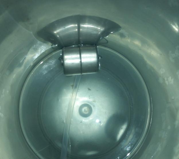
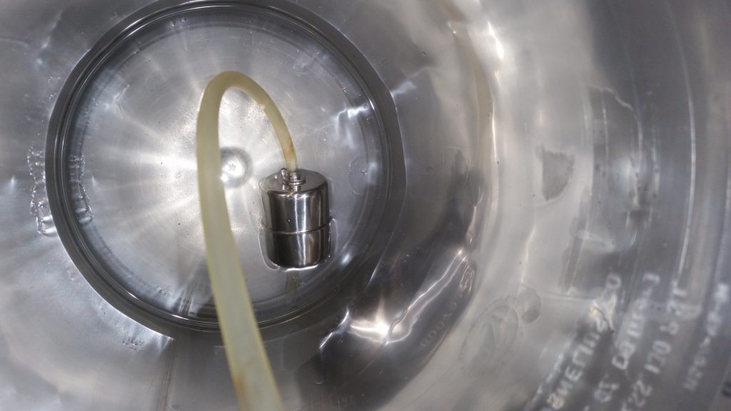
As you can see below, the float sits with the diptube under the water level.
You can fine-tune the float by adding more washers to the bottom side if your float does not behave properly.
Note, the clamps are not crimped. The only reason you would crimp them slightly is to get a tight (interference) fit on the silicone tube. This will allow you to adjust / fine tune and more importantly clean your diptube float assembly.
The list above will probably contain more parts than you need to make one float. ..
Feedback
I would appreciate some feedback on this new design if you decide to build mk2…
UPDATE 18.10
Mk3 is ready and working better than ever and way cheaper!
I have been a maker pretty much all my life. PCB fabrication has always interested me from constructing prototypes on vero board to toner transfers onto dual sided FR4 board.
As time went on, the through hole components gave way to the SMT parts that initially were OK to install by hand (eg 1206 and to some extent 0603).
My progression to 0402 parts and jittery flair for coffee in the morning has made it quite laborious to work with so I decided just like many makers out there to invest in a PCB assembly line.
Note, in this day and age with the likes of JLCPcb (AKA Shenzen JLC Electronics Co Ltd AKA JiaLiChuang (HongKong) Co Ltd), PCB fabrication at home is now relegated to “doing art” and no longer a practical nor time economical activity. So we will just focus on assembling fabricated PCBs using a commercially made Stencil.
The Process
Well this one is real simple. We will take a commercial assembly process and reduce it down we get the following process.
We will need a Solder Paste Printer, a pick and place machine and a reflow oven.
Solder Paste Printer
After much research and my own experiences setting up stencil jigs, I want a printer that allows fine scale control over the levelness of the pcb while “squeegeeing”.
Enter the 3040 Printer.
Features:
Work table size: 300*400mm (Pretty much standard low cost stencil from JLCPcb)
Locate mode: Benchmark or hole shape Dimension 540*370*350 mm
Weight: 25Kg
Pick & Place Machine
I want something that has some good reviews already and the thumbs up from fellow makers. I don’t need something with a million feeders but I do want something with around 20-30 feeders, a separate IC tray area and possibly tubed IC feeding capability.
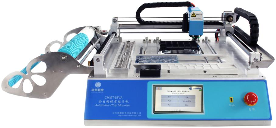
On a budget the following machine seems to be the way to go. The Charmhigh CHMT48VA.
Features:
Dimensions L 960mm*W 705mm*H 335mm
PCB Area 10*10~355*355mm <– More than enough for the stencil print size
XY Axis travel 400*460mm
Z axis move range 15mm
Pick and Place heads 2pcs
Mounting Speed:
With vision 3000~4000cph
Without vision 6000cph-7000cph
Working Precision ±0.025mm
Reels/Feeders/Stacks/Trays:
8mm=22 stack
12mm=4 stack
16mm=2 stack
24mm=1 stack
Front IC=14 stack
User-defined IC tray
Vacuum pump 2pcs in-built
Vision system Up view and down view dual cameras
Computer system inside Linux system inside,
CSV file By Protel 99SE ; Altium Designer and Eagle
Touch screen 7’’ (15.6cm*9.3cm) industry touch screen
Support packages 0402,0603,0805,1206,1210,3528,5050, SO-16,SOT-23,SOT-89,TO-252,SOP,QFN, LQFP….different kinds of IC (max size 22*22mm)
Reflow Oven
Again, lots of people out there with reviews on ovens. The Puhui T962 series seems to be bagged a lot but there are some fixes to get it working “properly”
I am going to go with the latest iteration the T962C and see how it goes. It has had a good review from the Superhouse guy (Andrew)…
Prediction: I have a feeling I’m going to have to build an oven myself….
My Purchases
These affiliate links help me in a small way at no extra cost to you. I have personally bought from these sellers and can verify they delivered the goods.
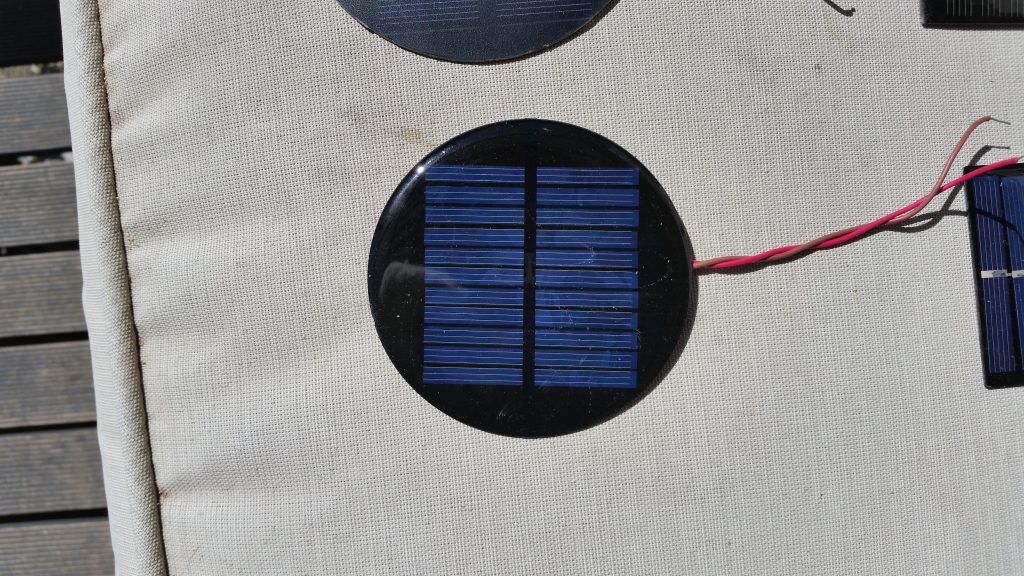
I have been searching for a solar panel to power some of my standalone ESP8266/32 projects and I have evaluated a bunch of panels. This particular panel got my attention because of its clamied power output and efficiency.
This is what the manufacturer/seller claims:
Specifications
Maximum power: 2W
Working current: 0.35A
Operating Voltage: 6V
System current: 6V
Open circuit voltage: 6.6V
Short circuit current: 350A
Parallel resistance: 0(ohm)
Series resistance: 1(ohm)
Conversion efficiency: 18(%)
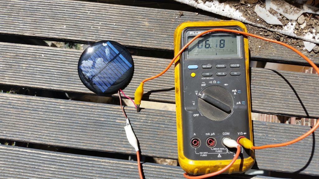
Of course the short circuit voltage is wrongly provided at 350A. Surely its 350mA?
Test & Application
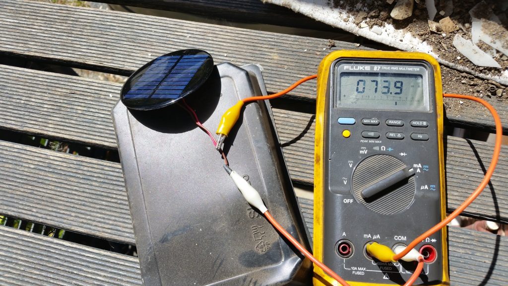
I did the tests for open circuit voltage and short circuit current using a Fluke 87 Multimeter.
Sunlight was at 30degree incident for Voc test. Came in at over 6V.
However disappointingly, the first short circuit test came in at a mere 64.9mA!
Second test with panel facing the sun directly came in at 73.9mA.
As you can see its nowhere near the claimed 350mA.