DIY Keg Floating Dip Tube !UPDATED Sept 2019!

Keg Residues

I’ve been homebrewing beer for the last 15 years. I started (like most) with a plastic fermenter / bucket and used hopped extracts with adjunct brewing sugars and then bottling with priming sugar.

Over the last 2 years I’ve migrated fully to kegs and I can say I don’t miss the bottling aspect of homebrewing! The only thing I do find is that beer that is dispensed towards the end of the keg tends to be extremely clear and refined.

So I asked the question, is it possible to draw from the top of the keg rather than the bottom and yet still be able to draw the full amount?

The answer came in the form of a float.

Plastic Fantastic

I am generally not a big fan of plastic items in contact with my food (yes beer is food). However I am a fan of and actively practice harm minimisation. After all we live in a world where economics rather than welfare dictates the nature of materials that come in contact with food. Harsh but true.

I am a big fan of food/surgical/marine grade stainless steel. Namely the 316 grade. It is highly non reactive in corrosive environments and does not leech out any estrogenic compounds. It could be leeching out chromium but hey what can I say; harm minimisation…

Float the idea

Here is a list of requirements I wrote up to help me design and build a device that could allow me to reduce sediment and improve clarity of the beer I was tapping off the keg:

  • Needs to fit easily through the opening of keg
  • Has to float in beer with ease
  • Must connect to the liquid port of the keg
  • It should be able to be removed for cleaning
  • No permanent modification to keg
  • Food safe materials only
  • Low cost of course 🙂 as I have 8 kegs to modify

So I can see I will require:

  1. A float of some kind
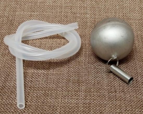
  2. A flexible tube that can connect to the liquid port and the float itself
  3. A method of stopping any sediment from entering the tube
  4. A method of weighing down the end that draws the liquid to ensure its always submerged.
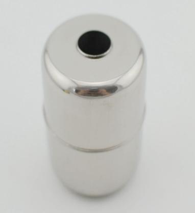
The components

the float

I found this nice float made out of stainless steel. It appears to be used for level sensors in potable drinking water tanks.
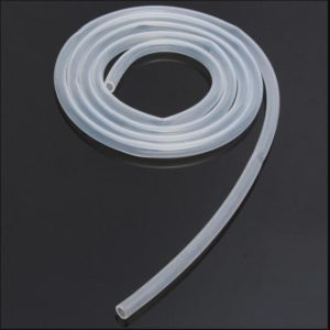
The tubeS

Silicone tubing is probably the safest material from a corrosion/leeching perspective for beer (acidic). You will need some 8mm tubing and a small amount of 10mm tubing to hold the filter inside the float.
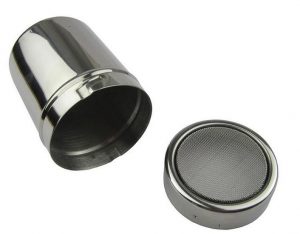
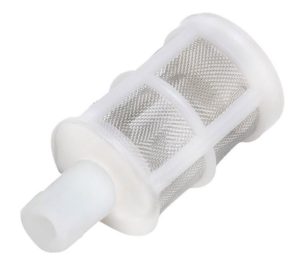
the filter

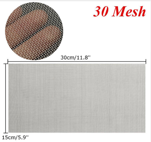
A filter like this is very useful in stopping any sediment/trub from being drawn into the liquid port. Its not a superfine mesh so its unlikely to block up. The mesh is made out of stainless steel and can be cleaned up easily. These filters are sold as “wine filters”.

the counterweight

The simplest counter weight I can think of is to use a stainless steel bolt attached to the removable end of the filter. To install the counterweight, drill an 8mm hole in the endcap and install the bolt and nut so that the thread is INSIDE the filter as shown below.


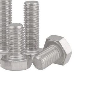
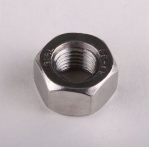
Make sure you use 316 grade and not 304!

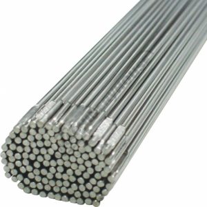
Replacement short Diptube

You can choose to cut your dip tube to attach the tubing but I didn’t want to permanently modify my kegs. The replacement diptube is actually used as the gas tube.

The Result

It will take you all but 15 minutes to make this.

Cut the tube to the suitable length for your keg. What you want is for the float to lay flat and the tube is just enough for that to happen. This simulates an empty keg scenario.

ADDITIONAL INFORMATION

I received some useful feedback from a reader recently so I’ve created this section to help with the build.

  1. The Filter has a removable bottom which aids in fitting the counterweight 
  2. To allow the filter to stay with the float you will need a 15mm section of 10mm diameter silicone hose fitted over the dip tube hose at the neck of the filter.

Sources for the parts in this project

You can help me out greatly by using the links below to purchase the parts in this project. There is no extra cost to you. In fact I can assure you of the seller’s complicity in successful orders and the pricing is fantastic.

Stainless Steel Float http://ali.pub/229u9j

Food grade Silicone Tube 8mm http://ali.pub/229umy

Food grade Silicone Tube 10mm http://ali.pub/229umy

Filters http://ali.pub/229uvp

Counterweight 316 M8x25mm Bolt http://ali.pub/2gmxjl

Counterweight 316 M8 Nut http://ali.pub/229v60

8mm Keg Diptube Short/Gas http://ali.pub/229vui

UPDATE: Off the shelf solution

I recently found that the Fermentasaurus SS Float assembly is available from Aliexpress.

It will do the job as long as you get a 8mm Keg short dip tube to replace the existing dip tube and just attach this SS float assembly to the supplied tube.

You will need:

Fermentasaurus Gen 1 SS Float + 60cm Silicone tubing: http://ali.pub/31196g

8mm Keg Diptube Short/Gas: http://ali.pub/229vui

Update September 2019

I have come up with a simpler solution for my fellow tight arse aussie brewers.

Check out my latest DIY Keg Floating Dip Tube Mk2

Contactor Coil Power Saver

If youre into electric car conversions or off grid power, you will come across large contactors / relays. The thing about them is they are great for having a mechanical disconnect from your battery to prevent draining or to changeover but they consume a lot of power when ON and liberate heat as a result.

Basic way

There are simple ways of creating a power saver circuit. The first is the DC polarised capacitor + resistor combination as shown below.

Basically it works as follows. The Voltage from Bat1 fills up Cb (blocking capacitor), thus energising the relay. Once the capacitor fills up, it’s impedance will rise to the point where the resistor comes into play. The value of the resistor is calculated as a dropping resistor value to keep the coil in a holding state. When Bat1 voltage is turned off, the coil will drain at the rate specified by the Rd,Cb network; t=1/RC.

This works OK except that you can see the holding voltage is directly proportional to the holding current via Ohms Principle (V=RI). This is fine for most applications. However if you want a certain holding voltage (as specified by the manufacturer’s datasheet) and want as low as possible holding current, you will need a better solution. To add, you need to ensure that the holding voltage is sufficient to withstand vibration (if your application calls for it).

Smart way

So you’re thinking in this day and age of microprocessors why not use a GPIO to PWM the relay/contactor coil via a mosfet to achieve current control while keeping voltage at a level you desire?

Well yes why not. Here are 3 ways.

(a) Easy to implement using a spare GPIO but no power saving

(b) You get Power saving through PWM but its fixed and requires tuning. Sometimes you don’t have PWM spare

(c) Use an interfacing IC that is driven by a GPIO HIGH LOW and let that IC do the work of managing power saving.

Uber-smart way (c)

Enter an IC from Texas Instruments called the DRV110. This particular IC is specifically designed to address the power consumption issues with energised coils in relays and contactors.

The implementation of the chip is simple and as follows.

As you can see it powers itself from the relay/contactor source. It can sense the current flowing through the coil to allow it to self manage the holding current.

The Peak, Hold and Keep (disengage delay) values can be set via resistors.

Voila! You have a separate holding voltage and holding current capability fully managed by this tiny IC.

Specifications of the IC.

You can see that the Vin value can be setup directly from the MCU or scavenged off the relay/contactor supply via a dropping resistor.

The Ven, turn on voltage works to 7V. So a 1.8V, 3.3V, 5V MCU GPIO can be used to turn it on and off.

The reason I really like this IC is the mosfet is external and up to you. So you can pick a nice low RdsON mosfet to keep the power / heat losses low.

If you wish to buy this IC for your project, please use the link below as it helps me out without extra cost to you.

Texas Instruments DRV110PWR:  http://ali.pub/20ovfr

Datasheet for DRV110: http://www.ti.com/product/DRV110/datasheet


Brewie: Sniffing the Control Board UART

Sticky Fingers

Being a hacker at heart means you just can’t leave things well enough alone. I really wanted to see if I could see how the touch screen control system software interfaced with the Brewie’s control board. Basically how the software tells the machine’s parts to work a recipe…

Incidentally, the Brewie’s control board is based around the ATMEGA2560. Could it be they are running an Arduino base in this?

The control board is nicely laid out with their own DC DC converted 5V rail from the 12V board supply. They are using MC33063A Buck converter ICs. Pretty standard stuff.

Datasheet here: http://www.ti.com/lit/ds/symlink/mc33063a-q1.pdf 

A bunch of control outputs driven by mosfets with protection diodes.

An op-amp circuit to provide weight sensor inputs to the micro.

The money shot

The prize here is the Connector Marked SERIAL0. The pinout of SERIAL0 is shown below:

It is obvious that the Touch screen control system which runs the Brewie software and is connected to the internet is able to flash a new firmware on the ATMEGA2560 since the DTR/Reset pin is exposed to it.

Well simple enough we can sniff this using another ATMEGA2560 or in my case an Arduino MEGA board.

The right connections

I soldered directly onto the pins of the Brewie board to allow me to have a connector outside the machine.

I now have a “DIAGNOSTIC” port on my Brewie that is sealed from moisture ready to use whenever I want to. I have plans to build a debug screen that allows me to see the raw data represented as more intuitive visuals compared to the crappy touch screen software…Sorry Brewie…it really does suck although its nice to see you are slowly but surely ironing out all the bugs…

The pinout connection is up to you but if you want to use my sketch then follow the pin configuration below:

The Sketch

I wrote a quick sketch that allows me to dump the Brewie’s “Conversation” to Serial output. I figured out that the communications are happening at a baud rate of 115200.

Download the Sketch  BrewieUARTSniffer.ino

Sample Output

It’s alive! I could now watch the Brewie’s conversation as it prepares a recipe.  The Brewie control board sends data every second or so in a fixed format with fields separated by TAB characters.

Download a log I captured: brewie-log-20171112-1900.log

Example at the start:

-----------------------------------------------------
Brewie Control Board UART Sniffer V1.0
Written by DrGus
Copyright 2017 DrGus
-----------------------------------------------------
Rst Brewie Control Board Reset!
Tx Brewie v1.0
Tx Copyright Brewie 2016
Rst Brewie Control Board Reset!
Tx #Brewie v1.0
Tx Copyright Brewie 2016
Tx Water level nullpoint: 333142
Tx -1 0 V5 89 0.0055075451 85.0000000000 85.0000000000 850.0000000000 850.0000000000 0 0 0 460 0 480 0 0 83 85.0000000000
Tx -1 0 V5 161 0.0099630868 30.8750000000 34.3750000000 308.0000000000 343.0000000000 0 0 0 460 0 480 0 0 45 30.0000000000
Tx -1 0 V5 251 0.0155325140 30.8750000000 34.3750000000 308.0000000000 343.0000000000 0 0 0 460 0 480 0 0 45 30.0000000000 

...and so on.

NOTE: The Rx, Rst and Tx prefixes are added by me to allow me to know which direction the information is going in. It is not present in the Brewie communications.

Analysing the data format

The data format appears to be fairly simple. I will provide the fields once I have reverse engineered it.

Example of a data sentence sent by the control board to the Touch Screen software. I picked this entry as it has some “rich” data in it.

1 199 60 0 V5 64983 5.1403689000 30.5625000000 23.9375000000 314.0000000000 251.0000000000 0 0 0 460 0 328 0 0 843 P103 2 0 1 0 0 0 0 0 0 0 0 0 0 0 255 0 90 5 0 0 1 29.5000000000
Field NumberFunction/Description
1Recipe Step/Increment. Default 0 or -1
2Time in seconds since the recipe started
3Time in seconds since the last step change or current Step Time
4Countdown time in seconds for a step to complete
5Firmware Version Number
If a prefix appears, its:
P103,V5 <- asking for next step
E101,V5 <- An error has occured
6Weight Raw value (Raw Water Level)
7Weight in kg (Water Level)
8Mash Tank Temperature in Degrees Centigrade
9Boil Tank Temperature in Degrees Centigrade
10Mash Tank Temperature as Centidegrees-Centigrade
11Boil Tank Temperature as Centidegrees-Centigrade
12Hall 1 RPM - Mash Pump
13Boil Pump
14Pump+Valve State
1->Pump ON
2->Pump ON+Mash to Boil Valve Open
15Hall 2 RPM
16Pump+Valve State
17Unknown
18Valve State
19Valve State
20Unknown
21Command Echo. When the Touch screen board sends a command to the controller, the controller echos it back in this field.
Default: blank
22System Temperature in Degrees Centigrade. There is a DS18B20 temperature sensor attached to the tray where the control board is fitted.

Analysing the command format

The command format also appears to be fairly simple. Below are the Brewie commands I have identified thus far. I will be analysing the structure soon to provide the functions of each field.

P80 12641.7 0 0.842726 1.22634

Command P80… It appears when the touch screen system first communicates with the control board

Command P101 “Step Init” So P101 <step count>

P103 0 1 0 0 0 0 0 0 0 0 0 0 0 0 0 50 0 1 0 0 0 
P103 1 0 0 0 0 540 0 0 0 0 0 0 0 0 0 0 1440 3 0 0 0 
P103 2 0 1 0 0 0 0 0 0 0 0 0 0 0 255 0 90 5 0 0 1
P103 3 1 0 0 0 0 0 0 0 0 0 0 0 0 0 50 30 1 0 0 0 
P103 4 0 1 0 640 0 0 0 0 0 0 0 0 255 0 0 180 2 0 1 0 
P103 5 0 1 0 640 700 0 0 0 0 0 0 0 255 0 0 900 6 0 1 0
P103 6 0 1 0 700 0 0 0 0 0 0 0 0 255 0 0 0 2 0 1 0 
P103 7 0 0 1 0 700 0 0 0 0 0 0 0 0 255 0 600 6 0 0 1 
P103 8 0 0 1 0 700 0 0 0 0 0 0 0 0 255 0 0 3 0 0 1 
P103 9 0 1 1 700 700 0 0 0 0 0 0 0 255 255 0 600 6 2 1 1 
P103 10 0 0 1 0 0 0 0 0 0 0 0 0 255 0 0 180 4 0 1 0 
P103 11 0 0 0 0 980 0 0 0 0 0 0 0 0 0 0 300 6 0 0 0 
P103 12 0 0 1 0 0 0 0 0 0 0 0 0 255 0 0 180 4 0 1 0 
P103 13 0 0 0 0 980 0 0 0 0 0 0 0 0 0 0 300 6 0 0 0 
P103 14 0 0 1 0 0 0 0 0 0 0 0 0 255 0 0 180 4 0 1 0 
P103 15 0 0 0 0 980 0 0 0 0 0 0 0 0 0 0 300 6 0 0 0 
P103 16 0 0 1 0 0 0 0 0 0 0 0 0 255 0 0 180 4 0 1 0 
P103 17 0 0 0 0 980 0 0 0 0 0 0 0 0 0 0 300 6 0 0 0 
P103 18 0 0 1 0 0 0 0 0 0 0 0 0 255 0 0 180 4 0 1 0 
P103 19 0 0 0 0 0 0 0 0 0 0 0 0 0 0 0 1800 7 0 0 0 
P103 20 0 0 0 0 0 1 0 0 0 0 0 0 0 255 0 300 6 3 0 1 
P103 21 0 0 0 0 0 1 1 0 0 0 0 0 0 255 0 300 6 3 0 1 
P103 22 0 0 0 0 0 1 1 1 0 0 0 0 0 255 0 180 6 3 0 1 
P103 23 0 0 0 0 0 1 1 1 1 0 0 0 0 255 0 120 6 3 0 1 
P103 24 0 0 0 0 0 0 0 0 0 1 0 0 0 255 0 120 6 0 0 1 
P103 25 0 0 0 0 230 0 0 0 0 1 255 0 0 255 0 1380 10 0 0 1 
P103 26 0 0 0 0 0 0 0 0 0 0 0 0 0 0 0 600 8 0 0 0

Command P103 … is the “Write Step” Command.

P103 <index> <inlet> <mashingvalve> <boilingvalve>  <mashing temp> <boiling temp>  <hop 1> <hop 2> <hop 3> <hop 4> <cooling> <fan> <outlet> <mashing pump> <boiling pump> <water level> <time> <condition> <auxCondition> <mashing One Way> <boiling One way>

Command P200 is “Start Brew”

Command P201… is “Pause Brew”

Command P202…is “Continue Brew”

Command P204  is “Next Step”

Command P999 tells the control board to STOP

Serial Logging to File

For those wondering how I captured the Serial log to file, I used a terminal window in Ubuntu.

Using this command:

(stty raw; cat > brewie-log-20171112-1900.log) < /dev/ttyUSB0

Sniffer Cable

If you don’t wish to solder directly to the board, you can make up an interfacing cable that has a Molex KK 2.54 Male socket and female plug with wires that extend out to an LED type connector as shown below.

If you want these connectors you can buy them using the link below as it helps me out without costing you anything extra.

http://ali.pub/20opbg

You can then create an external connection point via this cable set. These come in a pair (5pins female and male) pre-terminated for ease and are IP66 rated.

You can buy them using the link below as it helps me out without costing you anything extra.

http://ali.pub/20opva


Brewie: Adding an additional inlet for filtered water

Brewie B20 is a fully automatic all-grain wort producing machine. It can do up to 22L batches although its great for 19L. The four hop additions are automatic however you can keep going if you manually change the hops.

My Brewie Arrives

I recently became the owner of a Brewie Automatic Brewing Machine. The unit arrived in a well packed box with all the necessary items for creating the wort for all grain beer recipes.

One Fitting to Rule them All

One thing I immediately noticed and didn’t like was the fact that you could not choose the sources of water for wort chilling vs the wort itself. I wasn’t about to make my beer out of tap water and I also don’t want to waste filtered RO water for the chilling process. So I hacked it.

Bits you will need

You will need the following items to allow your Brewie to have two separate water inlets. The existing inlet is converted to only supply water to the chiller. A new inlet is created to supply filtered water to the brewing process circuit.

12vdc DN15 solenoid

The Brewie’s existing water distribution is achived via a single inlet DN20, dual solenoid valve that feeds the chiller circuit and the tank fill circuit.

The solenoid below has a DN15 (1/2″ BSP) thread inlet and a DN15 (1/2″ BSP) thread outlet. It has a 12Vdc coil with two spade terminals. These specifications are important for our modifications.

You can buy this solenoid on Aliexpress using my link as it helps me out without any extra cost to you.

http://ali.pub/20ka04

DN15 to 12mm barb adapter

This adapter goes onto the OUTLET of the solenoid. Note DN15 is 1/2″ BSP. Since we will be using the Brewie’s existing hose we need the barb to be 12mm.

You can buy this adapter on Aliexpress using my link as it helps me out without any extra cost to you.

http://ali.pub/31bc63

DN15 to 1/4″ QUICK FIT adapter

This adapter goes onto the INLET of the solenoid. Note DN15 is 1/2″ BSP. If you want to use a straight version of this adapter that is fine too.

You can buy this adapter on Aliexpress using my link as it helps me out without any extra cost to you.

http://ali.pub/20kacr

TOOLS REQUIRED
  1. Step drill bit 20mm hole required
  2. Drill machine
  3. Screwdrivers (Phillips)
  4. Pliers (to remove hoseclamps)
  5. Scissors (to cut hose)
Other Bits

You may think you need hose clamps but you don’t. Because we are removing a pipe from the Brewie there will the right amount of hose clamps to do the job.

Making the Modification

WARNING

Make sure the machine is FULLY DRAINED of liquids 
and the power has been DISCONNECTED before proceeding.

You will need to lay the machine on its front side / back side and then proceed to remove the bottom cover. Basically unscrew the four black feet and remove all of the phillips head screws EXCEPT the screws holding the fans in place.

You can choose to disconnect the fans from the Brewie Control Board or just leave them connected.

The next stage is to remove the hoses connected to the water inlet solenoids.

You should then remove the existing solenoid assembly and take note of the markings. My unit’s chiller solenoid wires were marked as “C”.

“14” Wires are the for the water inlet solenoid.

Re-route the “14” wires to the centre of the unit where the hop tanks are. You will need to undo some cable clips to do this.

Move the “C” wires from the existing solenoid to the other solenoid. We are doing this to move the chiller input solenoid to the back now.

Remove the backing plate shown below:

Drill a 20mm hole near the power cord inlet. This is where the new DC solenoid will meet the outside world as shown below.

Reassemble the backing plate and fit the solenoid into place. Plug in the rerouted solenoid control wires into this solenoid.

Route the hose in the following manner and secure using the left over hose clamps.

NOTE: There is a check valve on the Tee piece where the hose connects…make sure it is in the right direction if you need to remove it.

That’s it you’re done. Put everything back together and give the machine a test run. You will now be able to have a separate water inlet for your filtered water that is only used for making wort. Straight tap water is used to chill the wort…

Build your own Searzall head for under $10

Sears All

Well as it gets more difficult to source a Searzall torch head; the item has been unavailable for a while now even from Amazon….Amazingly the price isn’t exactly cheap….so I said fark it… Im building one.

Ok what do I need? Lets examine the unit itself…


It would appear that effectively its a radiant heat device. The “high temp mesh” is probably some stainless steel mesh that does not corrode and acts as the radiator.

Ok well this looks easy enough to build?

Analysis?

What would it take to build one?

  • A adapter that allows the head to float off the torch body to reduce the heat soak; this can be done using 316L stainless steel filler rod 1.6mm
  • A mesh  or series of meshes designed to sit at the edge of the flame envelope
  • A way of channeling the heat through the mesh

DIY Route

As I see it, you need a stainless steel chamber that is suspended from the torch head to prevent heat moving back into the torch. The front of the chamber needs to have mesh that is capable of handling the heat.

EDIT: If you want to create insulation, you could NEST two of the chambers; a smaller one inside the larger one separated by high temperature ceramic/glass wool.

Medium Chocolate Powder dispenser

I found a medium sized chocolate duster that is used for coffee art. The size of the medium unit is almost on par with the Searzall unit.

  • 6cm diameter
  • 8cm tall
  • Medium size

Available from Aliexpress. Please use my link below as it helps me out at no extra cost to you. Make sure you get the MEDIUM SIZE.


All you have to do is drill a 20mm hole in the base large enough to allow the flame from the torch to not heat the dispenser itself.

Here are a list of affiliate links for this shaker. Your support benefits me without extra costs to you.

Source 1: http://ali.pub/2h2bjd 

Source 2: http://ali.pub/2h2bqr

Source 3: http://ali.pub/2h2bqy

Source 4: http://ali.pub/2h2brq

STAINLESS MESH

You can get this Mesh online. The size/grade you are after is “30”.

You can get it on Aliexpress. Please use my link below as it helps me out at no extra cost to you. Make sure you get the SIZE 30. This is the size that worked best for me.

Also make sure you get enough to make plenty of spare screens for your searing tip. As intially while you set this thing up you may burn them up.

Take a sharp kitchen scissors and cut circles to suit the powder dispenser. You want the fit to be fairly tight. For my tip I used 2 screens together as per Searzall. I also left the original screen in the dispenser but you can choose to remove it.

Source 1: http://ali.pub/20k7lz

Source 2: http://ali.pub/2h2bvf

Source 3: http://ali.pub/2h2by5


Stainless Steel TIG Welding wire 1.6mm

I have plenty of TIG filler rods around. Why not use it as the frame for our torch head?


Basically bend into shape and tack weld to the dispenser. Bend the wires up toward the hole of the dispenser. Leave some excess so you can fine tune it to fit your torch adapter (next item).

DIY TORCH ADAPTER: length of ALUMINIUM MACHIning round

A short length of aluminium 25mm diameter by 25mm long in which a bore to suit your torch tip can be made with a lathe or a drill if you are careful. For my torch it was 15mm so I bored a hole using a 5/8″ (15.8mm) drill bit.

You will need to tap a thread for a grub screw to attach the head to your torch.

Additionally 3 holes need to be drilled in the side of this aluminium to the diameter of the wire / filler rod being  used…

the result

Well I must say for a few hours work it was worth it. It works like a dream….

Say goodbye to the ol “Torch Taste” and enter a level of culinary excellence worthy of a Michelin Star kitchen…