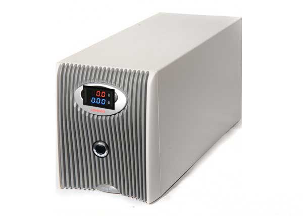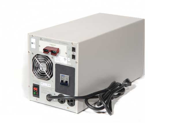
Being off-grid means energy freedom for me. However freedom from the grid also means attachment to the whims of nature and the waxing and waning cycles of light from the sun, intermittent wind.
There are days when my energy system storage gets low enough to warrant some stress about running out of power. The thing I found, there aren’t a lot of low cost options to bulk charging a DC bank of batteries properly and safely.
I can’t stress how important it is to have CC and CV capability otherwise you will most likely fry your batteries without any form of external voltage and current management!
Design
I decided to look into a cheap (ish) way building a bulk charger for my 2600Ah 48V battery bank. I settled upon the idea of using a low frequency transformer linear power supply from mains then passing that into some sort of CV/CC DC DC boost converter.
I came up with the following topology:

The idea would be to salvage a low frequency transformer from a high capacity UPS, rectify the low voltage output then feed it into the boost converter set to 54Vdc at 30A.
Self deprecation (sort of)
I know you’re thinking why go through all this trouble when you can just plug in the UPS into wall socket and break out the DC leads and plug it straight into the battery bank.
Well here is my list of cons:
- Non-resettable overcurrent protection – basically your bank will be much larger than the original battery bank in the UPS which means that you may exceed the current capability for charging of the UPS
- The charge rate isnt fantastic- I’ve noticed that the UPS in charger mode is actually a pretty slow charger for larger banks
- When power goes off it starts the inverter inside….which even at no load wastes power! I suppose you could unplug it or turn it off…I wanted a handsfree solution
- All those fans inside would waste a lot of power (the UPS I used had two fans that ran all the time!)
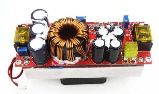
Boost Converter Module
A total monster unit…all pre-assembled for you!
Specifications:
- Output: 1800W
- Input voltage range: 10V-60V
- Output voltage range: 12V-90V
- Input current: 40A
- Output current: 22A (I was able to push to 30A at 54V out)
- Dynamic response speed: load current change 5% (300us)
- Conversion efficiency:
- 48V to 60V 8A (98.1%)
- 48V to 72V 8A (98.1%)
- 48V to 84V 8A (97.6%)
- 48V to 54V 30A (Efficiency TBA <– I will calculate and post soon)
- Load regulation: 10% to 50% load ((72V output))
- Temperature coefficient: 50% load
- Ripple & Noise: 20MHz Bandwidth (48V-72V 4A) 100mVp-p
- Switching frequency: VIN=48V VO=72V 4A (110khz)
- No-load current: VIN=48V VO=72V (18mA)
- Output short circuit protection: YES
- Input reverse protection: YES
- Working temperature: -20 65°C
- Temperature rise during work: 48V to 60V 5A (45°C)
- Over temperature protection: (60°C)
Modifications required:
- Breakout the current setting pot to an external panel mounted job. The CC pot on my module was a W502 or 5Kohm multi turn
- Remove the onboard fuses and replace with copper links (ONLY if you are running the external breaker)

Putting it together
Basically you find a UPS that runs on your country’s mains voltage (in my case thats 230Vac) or the generator’s output voltage and uses a 48V dc battery bank. The idea is you can use any external source of mains AC to drive this.
You strip out the PCB and control/display board but perhaps leaving a portion of the AC EMI filter circuitry (completely) optional.
Rewire the transformer so that the mains comes in and directly feeds the high voltage side of the transformer.
You then wire the low voltage secondary to a pair of diode bridge rectifier modules in parallel to give you some redundancy.
The “un-smoothed” rectified DC is fed into a bank of 3 x 10000uF capacitors rated to 63V or more. I suggest you go with 80V to be safe.
This is then fed into the input of the DC DC boost converter.
The boost converter is modified to have its on-board multi-turn constant current pot broken out into a panel mounted version. This then allows you to set the output current.
The output of the converter is then connected through the DC breaker, then the current shunt and then to the 50A Anderson connector at the back.
Note the voltage should be preset inside and I don’t recommend you break that out in case someone decided to crank out 90V and destroy your batteries and possibly your charger.
The “VOLTAMMETER”
Cut the front panel of the UPS and fit the voltmeter/ammeter combo. The unit needs 12-30V to work so use the buck XL7015 unit that can handle up to 80V input (see parts list). Wire the input of this converter to the DC smoothing bank and not the boost converter (why use up those precious watts from the converter?).
Wiring Guide
Below is just a rough wiring/schematic for the project. I leave it to you as an experienced engineer/technician/sparky to deal with the detail via your towering intellect and aeons of experience 🙂

Settings
Set the voltage output to between 54 and 56 volts depending on your battery bank type. Set the current to a few amps first to test things out.
UPDATE: I will be developing a MK2 version in which I will be using two of the modules examining the mosfets and current shunt used on the board to maximise the output current capability. I also plan to simplify the design.
Parts I used in this project
Below are a list of items I used in the project. These are affiliate links with Aliexpress that provide benefit to me without any extra cost to you. I appreciate your support of my work.
Compaq UPS 2200XR. <– Find a decent secondhand UPS with at least 1800VA 48V rating, you will find the transformer inside.
1800W 40A DC DC converter module CC CV
0-100V, 0-50A combination voltmeter/ammeter including 50A shunt
XL7015 v2: 5-80V to 12V Buck converter module
2x Anderson 50A red connectors


Would my new Honda EU 2200i generator power this charger?
Perhaps. You will have to test it out. I suspect you may need to include inrush current limiting. Essentially, you use a SPDT relay’s NC contact to introduce a drop resistor in series with the primary winding. This reduces the inrush current (energising current). Then, when the secondary reaches a minimum voltage (say 12V) it turns the relay on which connects mains to the primary winding through the NO contact…
I will publish this modification soon….I reckon it would be handy to have inrush limiting….