OMVL Dream XXI N DIY Communications Cable

Diagnostics

A while back my LPG system started playing up. Strangely enough while running on LPG the car would stall intermittently. To make matters worse, when it did stall I was unable to switch back over to petrol! This meant I had to pull over somehow, pull the ECU’s fuse to reset the ECU so that it would start up in petrol mode.

To start diagnosing things I figured I would need a serial cable to talk to the ECU. I looked out there and the cables ranged from USD$80 to over USD$200!

I thought to myself, after the Brewie UART sniffing project it wouldn’t be difficult to wire up a quick Serial interface to the laptop. This time however instead of logging I needed it to work with the OMVL Diagnostic Software.

The Interface

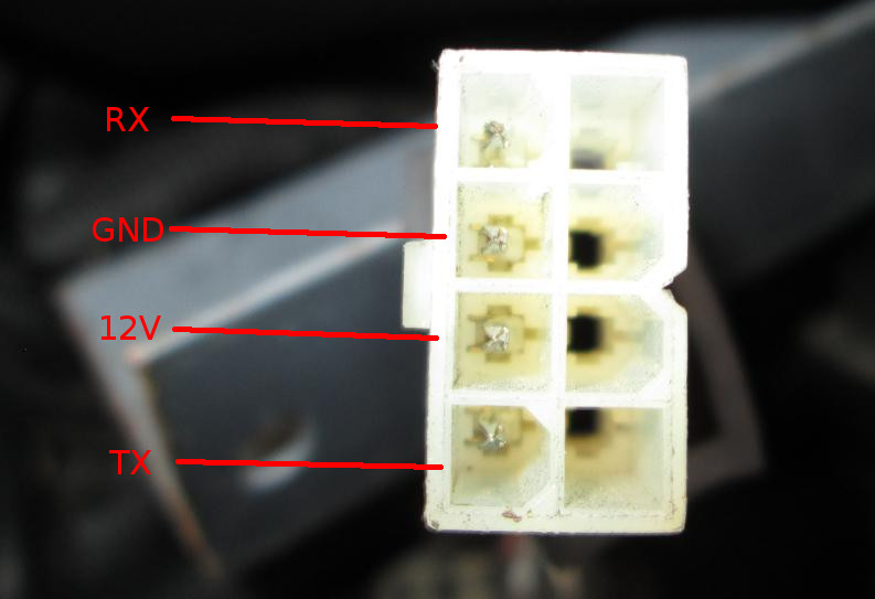
Simply put the OMVL has a 8 pin female Molex connector with only 4 pins fitted. With a multimeter I quickly figured out the following pin assignments:

Note: I couldnt work out just with a multimeter which was TX or RX. I just swapped them around until I got it working. They work at 5V levels.

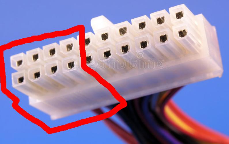
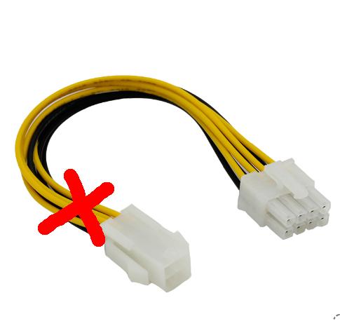
I also immediately recognised that the molex connector looked a LOT like part of the plug on an ATX PSU connector. Since I collect these PSUs for spart parts like fans, mosfets, heatsinks and hookup wire, I identified the part of the ATX connector that fit the OMVL serial interface plug.

Below is the part you will need:

Basically cut the connector so that only the part in red remains. It will fit the OMVL serial interface perfectly.

However if you don’t have spare PSUs or don’t want to sacrifice one, you can buy this portion of the cable and butcher that. Just cut it at the red X.

You can buy one from here at no extra cost to you but it benefits me:

http://ali.pub/2jquv5

FTDI to USB Adapter

I bought a cheap FTDI to USB adapter to form the interface between the ECU and the laptop’s USB port.


You can buy one from here at no extra cost to you but it benefits me:

http://ali.pub/2jqv2q

Connections

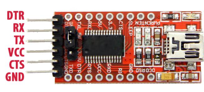
The FT232RL had the following pinout:

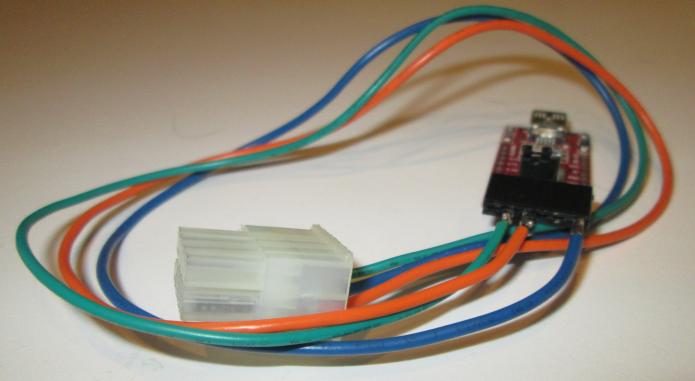
Basically follow the connection as shown below:

OMVL ConnectorFTDI Adapter
RXTX
GNDGND
12VDO NOT CONNECT
TXRX

Testing

Few points:

  • You may need the FTDI drivers for windows.
  • You may need to swap RX and TX if it does not work at first
  • Make sure you set the FT232RL jumper setting to 5V (NOT 3.3V)

The setup above successfully connected and I was able to diagnose my LPG ECU.

Hope this article was useful to you!

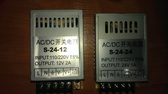
S-24-x 12V 2A or 24V 1A low cost power supply

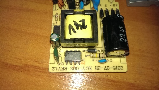
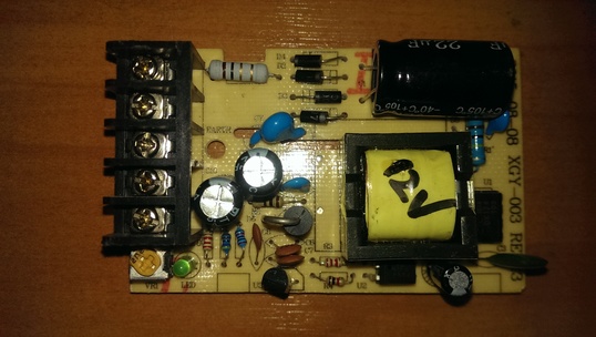
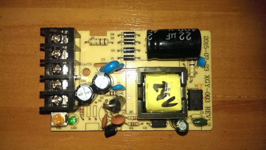
I recently came across this relatively cheap power supply for my projects. It features a single chip switch mode IC which has an integrated high voltage NPN transistor for the switching.

The design was curious because of the lack of filtering etc.

The Design

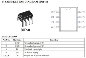
The power supply is built around the IC DK124. Essentially its quite a convenient package which requires a minimal number of support components.

The pinout of the IC is shown below.

The datasheet also shows you an application circuit with values and also how to calculate the transformer for your application.

Youtube’s bigclivedotcom has a nice video analysing/explaining the operation of the circuit so I won’t bore you with the details. However his version was a clone according to his comment(s).

The datasheet for this IC can be found here:
http://grupoautcomp.com.br/wp-content/uploads/2016/11/Specification-IC-DK124.pdf

If its not available you can download a summary here: Condensed-DK124.pdf

The Problem

Unfortunately the seller accidentally sent me a mix of 24V and 12V versions when I specifically ordered all 12V@2A versions.

Add to that the impending Chinese New Year Hiatus, I was left to figure out how to turn the 24V into a 12V.

Turns out 90% of the components inside are identical except for the feedback circuit…

I discovered that resistors R5, R6 and VR1 are the only differences between the two boards.

Below is a table of the values:

Part12V version24V version
R520K75K
R64K78K2
VR12K200R

The quickest conversion is to replace those parts verbatim. However i decided I would try to retain the pot and attempt to change the voltage divider to suit.

The feedback circuit

First I set the 12V version to output a stable 12.10V. At that point I measured the 2K potentiometer to see what value it read. It read 562R.

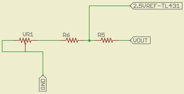
The simplified feedback circuit is as follows:

With VR1 set to 562R, the equivalent series resistance with R6 is 4700R+562R = 5262R or approx 5K3. The voltage at the TL431 ref pin would be 2.5V as expected.

So to retain the pot on the 24V version, I just need to figure out the voltage divider values that will bring the same 2.5V vref.

After some experimenting around I figured out to retain the 200R pot, I can use the following R5 and R6 values.

R5 = 18K and R6  = 4.7K while VR1 remains at 200R.

This will give a nice adjustable range of 10.5V to 12.1V

Purchase

If you are considering buying this power supply. May I offer my affiliate link which while it helps me out, costs you nothing extra. In fact I can vet the quality of the unit as shown in the photos.

http://ali.pub/27ybgf


Brewie: Sniffing the Control Board UART

Sticky Fingers

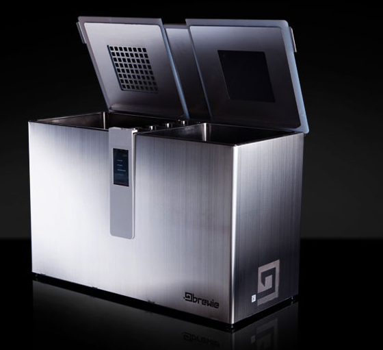
Being a hacker at heart means you just can’t leave things well enough alone. I really wanted to see if I could see how the touch screen control system software interfaced with the Brewie’s control board. Basically how the software tells the machine’s parts to work a recipe…

Incidentally, the Brewie’s control board is based around the ATMEGA2560. Could it be they are running an Arduino base in this?
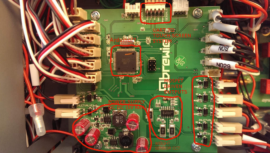
The control board is nicely laid out with their own DC DC converted 5V rail from the 12V board supply. They are using MC33063A Buck converter ICs. Pretty standard stuff.

Datasheet here: http://www.ti.com/lit/ds/symlink/mc33063a-q1.pdf 

A bunch of control outputs driven by mosfets with protection diodes.

An op-amp circuit to provide weight sensor inputs to the micro.

The money shot

The prize here is the Connector Marked SERIAL0. The pinout of SERIAL0 is shown below:
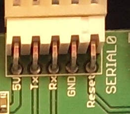
It is obvious that the Touch screen control system which runs the Brewie software and is connected to the internet is able to flash a new firmware on the ATMEGA2560 since the DTR/Reset pin is exposed to it.

Well simple enough we can sniff this using another ATMEGA2560 or in my case an Arduino MEGA board.

The right connections

I soldered directly onto the pins of the Brewie board to allow me to have a connector outside the machine.
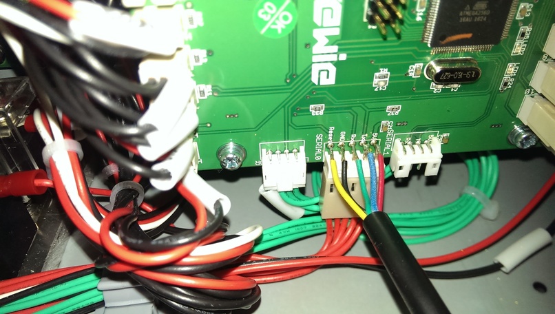
I now have a “DIAGNOSTIC” port on my Brewie that is sealed from moisture ready to use whenever I want to. I have plans to build a debug screen that allows me to see the raw data represented as more intuitive visuals compared to the crappy touch screen software…Sorry Brewie…it really does suck although its nice to see you are slowly but surely ironing out all the bugs…
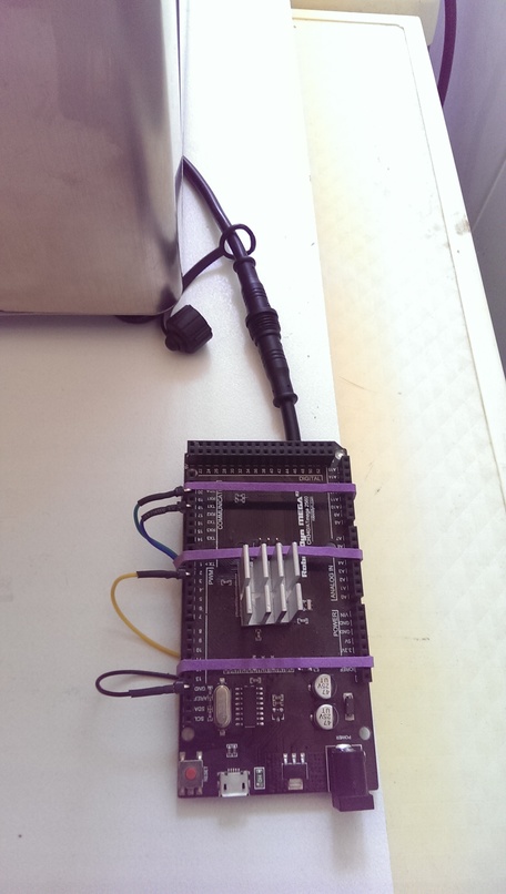
The pinout connection is up to you but if you want to use my sketch then follow the pin configuration below:

The Sketch

I wrote a quick sketch that allows me to dump the Brewie’s “Conversation” to Serial output. I figured out that the communications are happening at a baud rate of 115200.

Download the Sketch  BrewieUARTSniffer.ino

Sample Output

It’s alive! I could now watch the Brewie’s conversation as it prepares a recipe.  The Brewie control board sends data every second or so in a fixed format with fields separated by TAB characters.

Download a log I captured: brewie-log-20171112-1900.log

Example at the start:

-----------------------------------------------------
Brewie Control Board UART Sniffer V1.0
Written by DrGus
Copyright 2017 DrGus
-----------------------------------------------------
Rst Brewie Control Board Reset!
Tx Brewie v1.0
Tx Copyright Brewie 2016
Rst Brewie Control Board Reset!
Tx #Brewie v1.0
Tx Copyright Brewie 2016
Tx Water level nullpoint: 333142
Tx -1 0 V5 89 0.0055075451 85.0000000000 85.0000000000 850.0000000000 850.0000000000 0 0 0 460 0 480 0 0 83 85.0000000000
Tx -1 0 V5 161 0.0099630868 30.8750000000 34.3750000000 308.0000000000 343.0000000000 0 0 0 460 0 480 0 0 45 30.0000000000
Tx -1 0 V5 251 0.0155325140 30.8750000000 34.3750000000 308.0000000000 343.0000000000 0 0 0 460 0 480 0 0 45 30.0000000000 

...and so on.

NOTE: The Rx, Rst and Tx prefixes are added by me to allow me to know which direction the information is going in. It is not present in the Brewie communications.

Analysing the data format

The data format appears to be fairly simple. I will provide the fields once I have reverse engineered it.

Example of a data sentence sent by the control board to the Touch Screen software. I picked this entry as it has some “rich” data in it.

1 199 60 0 V5 64983 5.1403689000 30.5625000000 23.9375000000 314.0000000000 251.0000000000 0 0 0 460 0 328 0 0 843 P103 2 0 1 0 0 0 0 0 0 0 0 0 0 0 255 0 90 5 0 0 1 29.5000000000
Field NumberFunction/Description
1Recipe Step/Increment. Default 0 or -1
2Time in seconds since the recipe started
3Time in seconds since the last step change or current Step Time
4Countdown time in seconds for a step to complete
5Firmware Version Number
If a prefix appears, its:
P103,V5 <- asking for next step
E101,V5 <- An error has occured
6Weight Raw value (Raw Water Level)
7Weight in kg (Water Level)
8Mash Tank Temperature in Degrees Centigrade
9Boil Tank Temperature in Degrees Centigrade
10Mash Tank Temperature as Centidegrees-Centigrade
11Boil Tank Temperature as Centidegrees-Centigrade
12Hall 1 RPM - Mash Pump
13Boil Pump
14Pump+Valve State
1->Pump ON
2->Pump ON+Mash to Boil Valve Open
15Hall 2 RPM
16Pump+Valve State
17Unknown
18Valve State
19Valve State
20Unknown
21Command Echo. When the Touch screen board sends a command to the controller, the controller echos it back in this field.
Default: blank
22System Temperature in Degrees Centigrade. There is a DS18B20 temperature sensor attached to the tray where the control board is fitted.

Analysing the command format

The command format also appears to be fairly simple. Below are the Brewie commands I have identified thus far. I will be analysing the structure soon to provide the functions of each field.

P80 12641.7 0 0.842726 1.22634

Command P80… It appears when the touch screen system first communicates with the control board

Command P101 “Step Init” So P101 <step count>

P103 0 1 0 0 0 0 0 0 0 0 0 0 0 0 0 50 0 1 0 0 0 
P103 1 0 0 0 0 540 0 0 0 0 0 0 0 0 0 0 1440 3 0 0 0 
P103 2 0 1 0 0 0 0 0 0 0 0 0 0 0 255 0 90 5 0 0 1
P103 3 1 0 0 0 0 0 0 0 0 0 0 0 0 0 50 30 1 0 0 0 
P103 4 0 1 0 640 0 0 0 0 0 0 0 0 255 0 0 180 2 0 1 0 
P103 5 0 1 0 640 700 0 0 0 0 0 0 0 255 0 0 900 6 0 1 0
P103 6 0 1 0 700 0 0 0 0 0 0 0 0 255 0 0 0 2 0 1 0 
P103 7 0 0 1 0 700 0 0 0 0 0 0 0 0 255 0 600 6 0 0 1 
P103 8 0 0 1 0 700 0 0 0 0 0 0 0 0 255 0 0 3 0 0 1 
P103 9 0 1 1 700 700 0 0 0 0 0 0 0 255 255 0 600 6 2 1 1 
P103 10 0 0 1 0 0 0 0 0 0 0 0 0 255 0 0 180 4 0 1 0 
P103 11 0 0 0 0 980 0 0 0 0 0 0 0 0 0 0 300 6 0 0 0 
P103 12 0 0 1 0 0 0 0 0 0 0 0 0 255 0 0 180 4 0 1 0 
P103 13 0 0 0 0 980 0 0 0 0 0 0 0 0 0 0 300 6 0 0 0 
P103 14 0 0 1 0 0 0 0 0 0 0 0 0 255 0 0 180 4 0 1 0 
P103 15 0 0 0 0 980 0 0 0 0 0 0 0 0 0 0 300 6 0 0 0 
P103 16 0 0 1 0 0 0 0 0 0 0 0 0 255 0 0 180 4 0 1 0 
P103 17 0 0 0 0 980 0 0 0 0 0 0 0 0 0 0 300 6 0 0 0 
P103 18 0 0 1 0 0 0 0 0 0 0 0 0 255 0 0 180 4 0 1 0 
P103 19 0 0 0 0 0 0 0 0 0 0 0 0 0 0 0 1800 7 0 0 0 
P103 20 0 0 0 0 0 1 0 0 0 0 0 0 0 255 0 300 6 3 0 1 
P103 21 0 0 0 0 0 1 1 0 0 0 0 0 0 255 0 300 6 3 0 1 
P103 22 0 0 0 0 0 1 1 1 0 0 0 0 0 255 0 180 6 3 0 1 
P103 23 0 0 0 0 0 1 1 1 1 0 0 0 0 255 0 120 6 3 0 1 
P103 24 0 0 0 0 0 0 0 0 0 1 0 0 0 255 0 120 6 0 0 1 
P103 25 0 0 0 0 230 0 0 0 0 1 255 0 0 255 0 1380 10 0 0 1 
P103 26 0 0 0 0 0 0 0 0 0 0 0 0 0 0 0 600 8 0 0 0

Command P103 … is the “Write Step” Command.

P103 <index> <inlet> <mashingvalve> <boilingvalve>  <mashing temp> <boiling temp>  <hop 1> <hop 2> <hop 3> <hop 4> <cooling> <fan> <outlet> <mashing pump> <boiling pump> <water level> <time> <condition> <auxCondition> <mashing One Way> <boiling One way>

Command P200 is “Start Brew”

Command P201… is “Pause Brew”

Command P202…is “Continue Brew”

Command P204  is “Next Step”

Command P999 tells the control board to STOP

Serial Logging to File

For those wondering how I captured the Serial log to file, I used a terminal window in Ubuntu.

Using this command:

(stty raw; cat > brewie-log-20171112-1900.log) < /dev/ttyUSB0

Sniffer Cable

If you don’t wish to solder directly to the board, you can make up an interfacing cable that has a Molex KK 2.54 Male socket and female plug with wires that extend out to an LED type connector as shown below.
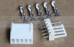
If you want these connectors you can buy them using the link below as it helps me out without costing you anything extra.

http://ali.pub/20opbg

You can then create an external connection point via this cable set. These come in a pair (5pins female and male) pre-terminated for ease and are IP66 rated.
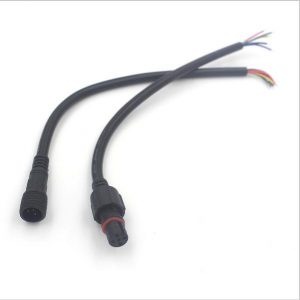
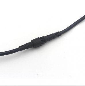
You can buy them using the link below as it helps me out without costing you anything extra.

http://ali.pub/20opva


Brewie: Adding an additional inlet for filtered water

Brewie B20 is a fully automatic all-grain wort producing machine. It can do up to 22L batches although its great for 19L. The four hop additions are automatic however you can keep going if you manually change the hops.

My Brewie Arrives

I recently became the owner of a Brewie Automatic Brewing Machine. The unit arrived in a well packed box with all the necessary items for creating the wort for all grain beer recipes.

One Fitting to Rule them All

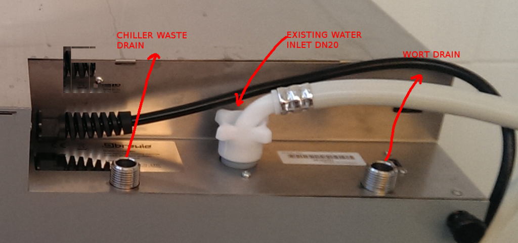
One thing I immediately noticed and didn’t like was the fact that you could not choose the sources of water for wort chilling vs the wort itself. I wasn’t about to make my beer out of tap water and I also don’t want to waste filtered RO water for the chilling process. So I hacked it.

Bits you will need

You will need the following items to allow your Brewie to have two separate water inlets. The existing inlet is converted to only supply water to the chiller. A new inlet is created to supply filtered water to the brewing process circuit.

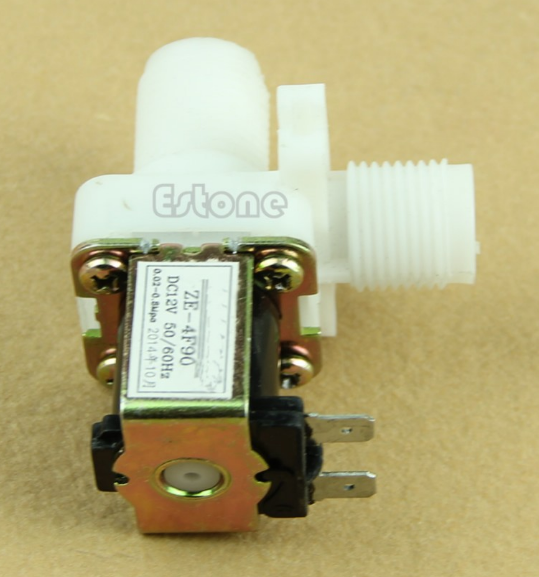
12vdc DN15 solenoid

The Brewie’s existing water distribution is achived via a single inlet DN20, dual solenoid valve that feeds the chiller circuit and the tank fill circuit.

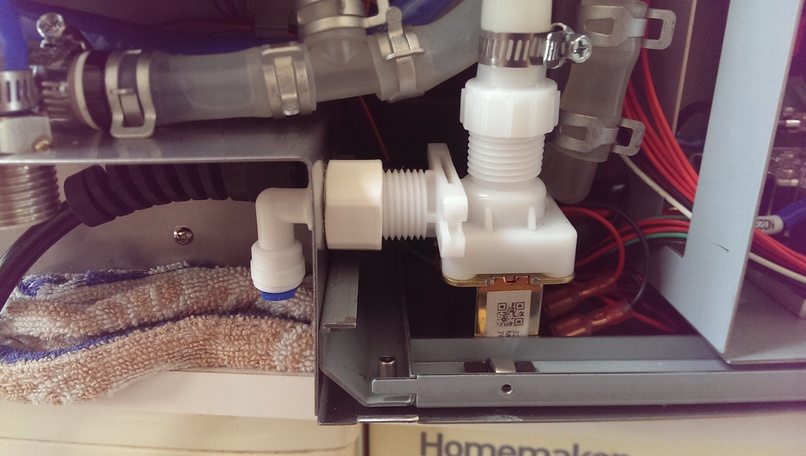
The solenoid below has a DN15 (1/2″ BSP) thread inlet and a DN15 (1/2″ BSP) thread outlet. It has a 12Vdc coil with two spade terminals. These specifications are important for our modifications.

You can buy this solenoid on Aliexpress using my link as it helps me out without any extra cost to you.

http://ali.pub/20ka04

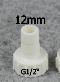
DN15 to 12mm barb adapter

This adapter goes onto the OUTLET of the solenoid. Note DN15 is 1/2″ BSP. Since we will be using the Brewie’s existing hose we need the barb to be 12mm.

You can buy this adapter on Aliexpress using my link as it helps me out without any extra cost to you.

http://ali.pub/31bc63

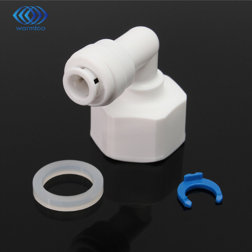
DN15 to 1/4″ QUICK FIT adapter

This adapter goes onto the INLET of the solenoid. Note DN15 is 1/2″ BSP. If you want to use a straight version of this adapter that is fine too.

You can buy this adapter on Aliexpress using my link as it helps me out without any extra cost to you.

http://ali.pub/20kacr

TOOLS REQUIRED
  1. Step drill bit 20mm hole required
  2. Drill machine
  3. Screwdrivers (Phillips)
  4. Pliers (to remove hoseclamps)
  5. Scissors (to cut hose)
Other Bits

You may think you need hose clamps but you don’t. Because we are removing a pipe from the Brewie there will the right amount of hose clamps to do the job.

Making the Modification

WARNING

Make sure the machine is FULLY DRAINED of liquids 
and the power has been DISCONNECTED before proceeding.

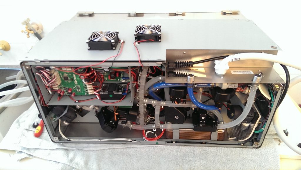
You will need to lay the machine on its front side / back side and then proceed to remove the bottom cover. Basically unscrew the four black feet and remove all of the phillips head screws EXCEPT the screws holding the fans in place.

You can choose to disconnect the fans from the Brewie Control Board or just leave them connected.

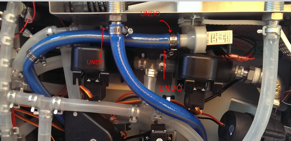
The next stage is to remove the hoses connected to the water inlet solenoids.

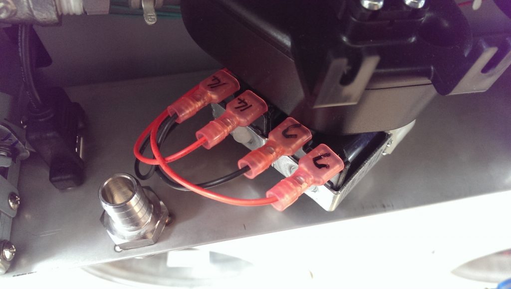
You should then remove the existing solenoid assembly and take note of the markings. My unit’s chiller solenoid wires were marked as “C”.

“14” Wires are the for the water inlet solenoid.

Re-route the “14” wires to the centre of the unit where the hop tanks are. You will need to undo some cable clips to do this.

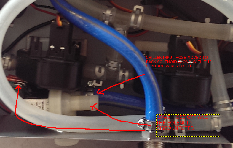
Move the “C” wires from the existing solenoid to the other solenoid. We are doing this to move the chiller input solenoid to the back now.

Remove the backing plate shown below:

Drill a 20mm hole near the power cord inlet. This is where the new DC solenoid will meet the outside world as shown below.

Reassemble the backing plate and fit the solenoid into place. Plug in the rerouted solenoid control wires into this solenoid.

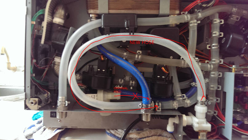
Route the hose in the following manner and secure using the left over hose clamps.

NOTE: There is a check valve on the Tee piece where the hose connects…make sure it is in the right direction if you need to remove it.

That’s it you’re done. Put everything back together and give the machine a test run. You will now be able to have a separate water inlet for your filtered water that is only used for making wort. Straight tap water is used to chill the wort…