Contactor Coil Power Saver

If youre into electric car conversions or off grid power, you will come across large contactors / relays. The thing about them is they are great for having a mechanical disconnect from your battery to prevent draining or to changeover but they consume a lot of power when ON and liberate heat as a result.

Basic way

There are simple ways of creating a power saver circuit. The first is the DC polarised capacitor + resistor combination as shown below.

Basically it works as follows. The Voltage from Bat1 fills up Cb (blocking capacitor), thus energising the relay. Once the capacitor fills up, it’s impedance will rise to the point where the resistor comes into play. The value of the resistor is calculated as a dropping resistor value to keep the coil in a holding state. When Bat1 voltage is turned off, the coil will drain at the rate specified by the Rd,Cb network; t=1/RC.

This works OK except that you can see the holding voltage is directly proportional to the holding current via Ohms Principle (V=RI). This is fine for most applications. However if you want a certain holding voltage (as specified by the manufacturer’s datasheet) and want as low as possible holding current, you will need a better solution. To add, you need to ensure that the holding voltage is sufficient to withstand vibration (if your application calls for it).

Smart way

So you’re thinking in this day and age of microprocessors why not use a GPIO to PWM the relay/contactor coil via a mosfet to achieve current control while keeping voltage at a level you desire?

Well yes why not. Here are 3 ways.

(a) Easy to implement using a spare GPIO but no power saving

(b) You get Power saving through PWM but its fixed and requires tuning. Sometimes you don’t have PWM spare

(c) Use an interfacing IC that is driven by a GPIO HIGH LOW and let that IC do the work of managing power saving.

Uber-smart way (c)

Enter an IC from Texas Instruments called the DRV110. This particular IC is specifically designed to address the power consumption issues with energised coils in relays and contactors.

The implementation of the chip is simple and as follows.

As you can see it powers itself from the relay/contactor source. It can sense the current flowing through the coil to allow it to self manage the holding current.

The Peak, Hold and Keep (disengage delay) values can be set via resistors.

Voila! You have a separate holding voltage and holding current capability fully managed by this tiny IC.

Specifications of the IC.

You can see that the Vin value can be setup directly from the MCU or scavenged off the relay/contactor supply via a dropping resistor.

The Ven, turn on voltage works to 7V. So a 1.8V, 3.3V, 5V MCU GPIO can be used to turn it on and off.

The reason I really like this IC is the mosfet is external and up to you. So you can pick a nice low RdsON mosfet to keep the power / heat losses low.

If you wish to buy this IC for your project, please use the link below as it helps me out without extra cost to you.

Texas Instruments DRV110PWR:  http://ali.pub/20ovfr

Datasheet for DRV110: http://www.ti.com/product/DRV110/datasheet


Build your own Searzall head for under $10

Sears All

Well as it gets more difficult to source a Searzall torch head; the item has been unavailable for a while now even from Amazon….Amazingly the price isn’t exactly cheap….so I said fark it… Im building one.

Ok what do I need? Lets examine the unit itself…


It would appear that effectively its a radiant heat device. The “high temp mesh” is probably some stainless steel mesh that does not corrode and acts as the radiator.

Ok well this looks easy enough to build?

Analysis?

What would it take to build one?

  • A adapter that allows the head to float off the torch body to reduce the heat soak; this can be done using 316L stainless steel filler rod 1.6mm
  • A mesh  or series of meshes designed to sit at the edge of the flame envelope
  • A way of channeling the heat through the mesh

DIY Route

As I see it, you need a stainless steel chamber that is suspended from the torch head to prevent heat moving back into the torch. The front of the chamber needs to have mesh that is capable of handling the heat.

EDIT: If you want to create insulation, you could NEST two of the chambers; a smaller one inside the larger one separated by high temperature ceramic/glass wool.

Medium Chocolate Powder dispenser

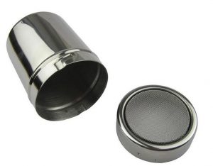
I found a medium sized chocolate duster that is used for coffee art. The size of the medium unit is almost on par with the Searzall unit.

  • 6cm diameter
  • 8cm tall
  • Medium size

Available from Aliexpress. Please use my link below as it helps me out at no extra cost to you. Make sure you get the MEDIUM SIZE.


All you have to do is drill a 20mm hole in the base large enough to allow the flame from the torch to not heat the dispenser itself.

Here are a list of affiliate links for this shaker. Your support benefits me without extra costs to you.

Source 1: http://ali.pub/2h2bjd 

Source 2: http://ali.pub/2h2bqr

Source 3: http://ali.pub/2h2bqy

Source 4: http://ali.pub/2h2brq

STAINLESS MESH

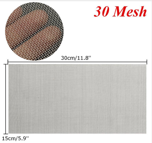
You can get this Mesh online. The size/grade you are after is “30”.

You can get it on Aliexpress. Please use my link below as it helps me out at no extra cost to you. Make sure you get the SIZE 30. This is the size that worked best for me.

Also make sure you get enough to make plenty of spare screens for your searing tip. As intially while you set this thing up you may burn them up.

Take a sharp kitchen scissors and cut circles to suit the powder dispenser. You want the fit to be fairly tight. For my tip I used 2 screens together as per Searzall. I also left the original screen in the dispenser but you can choose to remove it.

Source 1: http://ali.pub/20k7lz

Source 2: http://ali.pub/2h2bvf

Source 3: http://ali.pub/2h2by5


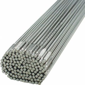
Stainless Steel TIG Welding wire 1.6mm

I have plenty of TIG filler rods around. Why not use it as the frame for our torch head?


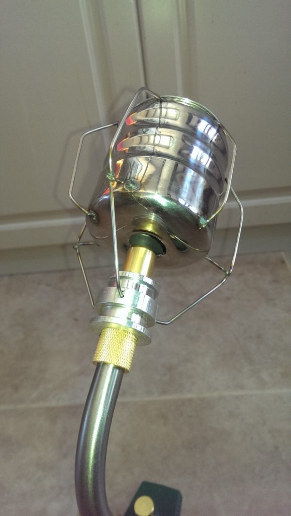
Basically bend into shape and tack weld to the dispenser. Bend the wires up toward the hole of the dispenser. Leave some excess so you can fine tune it to fit your torch adapter (next item).

DIY TORCH ADAPTER: length of ALUMINIUM MACHIning round

A short length of aluminium 25mm diameter by 25mm long in which a bore to suit your torch tip can be made with a lathe or a drill if you are careful. For my torch it was 15mm so I bored a hole using a 5/8″ (15.8mm) drill bit.

You will need to tap a thread for a grub screw to attach the head to your torch.

Additionally 3 holes need to be drilled in the side of this aluminium to the diameter of the wire / filler rod being  used…

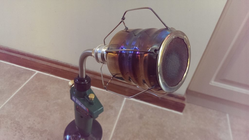
the result

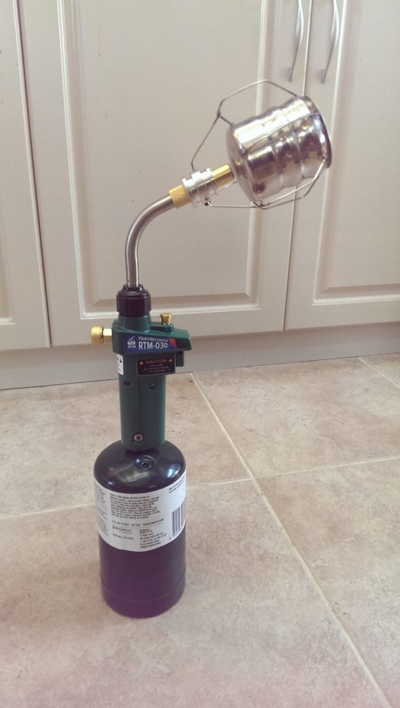
Well I must say for a few hours work it was worth it. It works like a dream….

Say goodbye to the ol “Torch Taste” and enter a level of culinary excellence worthy of a Michelin Star kitchen…