Sticky Fingers
Being a hacker at heart means you just can’t leave things well enough alone. I really wanted to see if I could see how the touch screen control system software interfaced with the Brewie’s control board. Basically how the software tells the machine’s parts to work a recipe…
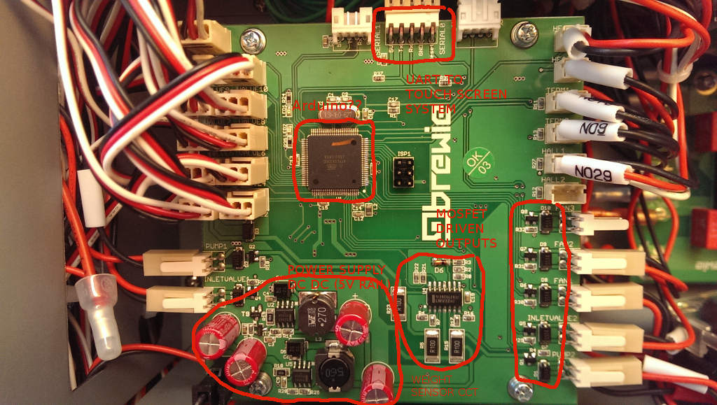
Incidentally, the Brewie’s control board is based around the ATMEGA2560. Could it be they are running an Arduino base in this?
The control board is nicely laid out with their own DC DC converted 5V rail from the 12V board supply. They are using MC33063A Buck converter ICs. Pretty standard stuff.
Datasheet here: http://www.ti.com/lit/ds/symlink/mc33063a-q1.pdf
A bunch of control outputs driven by mosfets with protection diodes.
An op-amp circuit to provide weight sensor inputs to the micro.
The money shot
The prize here is the Connector Marked SERIAL0. The pinout of SERIAL0 is shown below:
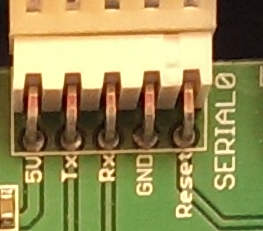
It is obvious that the Touch screen control system which runs the Brewie software and is connected to the internet is able to flash a new firmware on the ATMEGA2560 since the DTR/Reset pin is exposed to it.
Well simple enough we can sniff this using another ATMEGA2560 or in my case an Arduino MEGA board.
The right connections
I soldered directly onto the pins of the Brewie board to allow me to have a connector outside the machine.
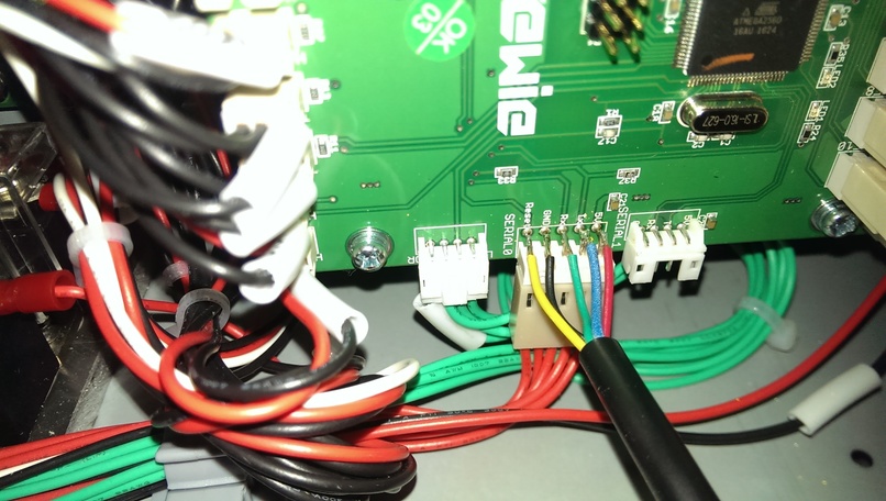
I now have a “DIAGNOSTIC” port on my Brewie that is sealed from moisture ready to use whenever I want to. I have plans to build a debug screen that allows me to see the raw data represented as more intuitive visuals compared to the crappy touch screen software…Sorry Brewie…it really does suck although its nice to see you are slowly but surely ironing out all the bugs…
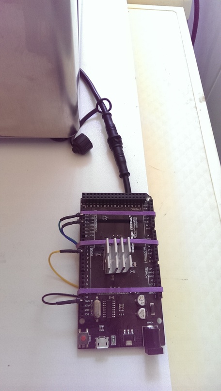
The pinout connection is up to you but if you want to use my sketch then follow the pin configuration below:

The Sketch
I wrote a quick sketch that allows me to dump the Brewie’s “Conversation” to Serial output. I figured out that the communications are happening at a baud rate of 115200.
Download the Sketch BrewieUARTSniffer.ino
Sample Output
It’s alive! I could now watch the Brewie’s conversation as it prepares a recipe. The Brewie control board sends data every second or so in a fixed format with fields separated by TAB characters.
Download a log I captured: brewie-log-20171112-1900.log
Example at the start:
-----------------------------------------------------
Brewie Control Board UART Sniffer V1.0
Written by DrGus
Copyright 2017 DrGus
-----------------------------------------------------
Rst Brewie Control Board Reset!
Tx Brewie v1.0
Tx Copyright Brewie 2016
Rst Brewie Control Board Reset!
Rst Brewie Control Board Reset!
Tx #Brewie v1.0
Tx Copyright Brewie 2016
Tx Water level nullpoint: 333142
Tx -1 0 V5 89 0.0055075451 85.0000000000 85.0000000000 850.0000000000 850.0000000000 0 0 0 460 0 480 0 0 83 85.0000000000
Tx -1 0 V5 161 0.0099630868 30.8750000000 34.3750000000 308.0000000000 343.0000000000 0 0 0 460 0 480 0 0 45 30.0000000000
Tx -1 0 V5 251 0.0155325140 30.8750000000 34.3750000000 308.0000000000 343.0000000000 0 0 0 460 0 480 0 0 45 30.0000000000

...and so on.
NOTE: The Rx, Rst and Tx prefixes are added by me to allow me to know which direction the information is going in. It is not present in the Brewie communications.
Analysing the data format
The data format appears to be fairly simple. I will provide the fields once I have reverse engineered it.
Example of a data sentence sent by the control board to the Touch Screen software. I picked this entry as it has some “rich” data in it.
1 199 60 0 V5 64983 5.1403689000 30.5625000000 23.9375000000 314.0000000000 251.0000000000 0 0 0 460 0 328 0 0 843 P103 2 0 1 0 0 0 0 0 0 0 0 0 0 0 255 0 90 5 0 0 1 29.5000000000
| Field Number | Function/Description |
|---|---|
| 1 | Recipe Step/Increment. Default 0 or -1 |
| 2 | Time in seconds since the recipe started |
| 3 | Time in seconds since the last step change or current Step Time |
| 4 | Countdown time in seconds for a step to complete |
| 5 | Firmware Version Number If a prefix appears, its: P103,V5 <- asking for next step E101,V5 <- An error has occured |
| 6 | Weight Raw value (Raw Water Level) |
| 7 | Weight in kg (Water Level) |
| 8 | Mash Tank Temperature in Degrees Centigrade |
| 9 | Boil Tank Temperature in Degrees Centigrade |
| 10 | Mash Tank Temperature as Centidegrees-Centigrade |
| 11 | Boil Tank Temperature as Centidegrees-Centigrade |
| 12 | Hall 1 RPM - Mash Pump |
| 13 | Boil Pump |
| 14 | Pump+Valve State 1->Pump ON 2->Pump ON+Mash to Boil Valve Open |
| 15 | Hall 2 RPM |
| 16 | Pump+Valve State |
| 17 | Unknown |
| 18 | Valve State |
| 19 | Valve State |
| 20 | Unknown |
| 21 | Command Echo. When the Touch screen board sends a command to the controller, the controller echos it back in this field. Default: blank |
| 22 | System Temperature in Degrees Centigrade. There is a DS18B20 temperature sensor attached to the tray where the control board is fitted. |
Analysing the command format
The command format also appears to be fairly simple. Below are the Brewie commands I have identified thus far. I will be analysing the structure soon to provide the functions of each field.
P80 12641.7 0 0.842726 1.22634
Command P80… It appears when the touch screen system first communicates with the control board
Command P101 “Step Init” So P101 <step count>
P103 0 1 0 0 0 0 0 0 0 0 0 0 0 0 0 50 0 1 0 0 0
P103 1 0 0 0 0 540 0 0 0 0 0 0 0 0 0 0 1440 3 0 0 0
P103 2 0 1 0 0 0 0 0 0 0 0 0 0 0 255 0 90 5 0 0 1
P103 3 1 0 0 0 0 0 0 0 0 0 0 0 0 0 50 30 1 0 0 0
P103 4 0 1 0 640 0 0 0 0 0 0 0 0 255 0 0 180 2 0 1 0
P103 5 0 1 0 640 700 0 0 0 0 0 0 0 255 0 0 900 6 0 1 0
P103 6 0 1 0 700 0 0 0 0 0 0 0 0 255 0 0 0 2 0 1 0
P103 7 0 0 1 0 700 0 0 0 0 0 0 0 0 255 0 600 6 0 0 1
P103 8 0 0 1 0 700 0 0 0 0 0 0 0 0 255 0 0 3 0 0 1
P103 9 0 1 1 700 700 0 0 0 0 0 0 0 255 255 0 600 6 2 1 1
P103 10 0 0 1 0 0 0 0 0 0 0 0 0 255 0 0 180 4 0 1 0
P103 11 0 0 0 0 980 0 0 0 0 0 0 0 0 0 0 300 6 0 0 0
P103 12 0 0 1 0 0 0 0 0 0 0 0 0 255 0 0 180 4 0 1 0
P103 13 0 0 0 0 980 0 0 0 0 0 0 0 0 0 0 300 6 0 0 0
P103 14 0 0 1 0 0 0 0 0 0 0 0 0 255 0 0 180 4 0 1 0
P103 15 0 0 0 0 980 0 0 0 0 0 0 0 0 0 0 300 6 0 0 0
P103 16 0 0 1 0 0 0 0 0 0 0 0 0 255 0 0 180 4 0 1 0
P103 17 0 0 0 0 980 0 0 0 0 0 0 0 0 0 0 300 6 0 0 0
P103 18 0 0 1 0 0 0 0 0 0 0 0 0 255 0 0 180 4 0 1 0
P103 19 0 0 0 0 0 0 0 0 0 0 0 0 0 0 0 1800 7 0 0 0
P103 20 0 0 0 0 0 1 0 0 0 0 0 0 0 255 0 300 6 3 0 1
P103 21 0 0 0 0 0 1 1 0 0 0 0 0 0 255 0 300 6 3 0 1
P103 22 0 0 0 0 0 1 1 1 0 0 0 0 0 255 0 180 6 3 0 1
P103 23 0 0 0 0 0 1 1 1 1 0 0 0 0 255 0 120 6 3 0 1
P103 24 0 0 0 0 0 0 0 0 0 1 0 0 0 255 0 120 6 0 0 1
P103 25 0 0 0 0 230 0 0 0 0 1 255 0 0 255 0 1380 10 0 0 1
P103 26 0 0 0 0 0 0 0 0 0 0 0 0 0 0 0 600 8 0 0 0
Command P103 … is the “Write Step” Command.
P103 <index> <inlet> <mashingvalve> <boilingvalve> <mashing temp> <boiling temp> <hop 1> <hop 2> <hop 3> <hop 4> <cooling> <fan> <outlet> <mashing pump> <boiling pump> <water level> <time> <condition> <auxCondition> <mashing One Way> <boiling One way>
Command P200 is “Start Brew”
Command P201… is “Pause Brew”
Command P202…is “Continue Brew”
Command P204 is “Next Step”
Command P999 tells the control board to STOP
Serial Logging to File
For those wondering how I captured the Serial log to file, I used a terminal window in Ubuntu.
Using this command:

(stty raw; cat > brewie-log-20171112-1900.log) < /dev/ttyUSB0
Sniffer Cable
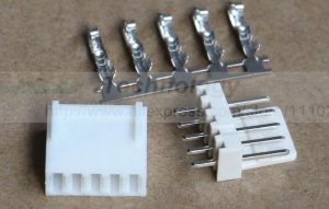
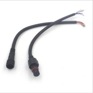
If you don’t wish to solder directly to the board, you can make up an interfacing cable that has a Molex KK 2.54 Male socket and female plug with wires that extend out to an LED type connector as shown below.
If you want these connectors you can buy them using the link below as it helps me out without costing you anything extra.
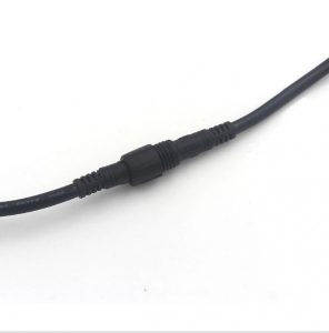
You can then create an external connection point via this cable set. These come in a pair (5pins female and male) pre-terminated for ease and are IP66 rated.
You can buy them using the link below as it helps me out without costing you anything extra.

