Grid Tied Solar Power
As the price of electricity soars in Australia, solar power starts to become more financially logical pathway with much less total cost of ownership times (TCO).
We can go down the route of getting a grid tied system using the STCs available to our homes but the usual topology is a DC to AC coupled system via a grid tie inverter. The power is fed back through the meter and you receive a modest return on your investment. If you were to then run your hot water heater you would still be behind…
Rheem 250L Tank
The unit I have is a Rheem 250L. Specs are:

Direct Current
A hot water heater is generally a resistive element (almost ideal resistance) rated to 240Vac (for a 3600W element) use. This translates to an operating current of 15A.
The beauty of a resistance is that it does not really matter if the voltage is AC or DC. A suitable way of running the heater directly off solar is to wire the panels in way such that the Vmp and Imp match closely the operating voltage, current and resistance of the element.
In my case, I have a Rheem Model 111250 250L single element heater. It has a 3600W element. The cold DC resistance of the element measures at 15.3Ω. The expected current required is 15A.
The panels I got for this exercise are Trinasolar TSM-250 PC/PA05A.

Specs:
- Pmp 250W
- Vmp 30.5V
- Imp 8.2A
- Voc 37.8V
- Imp 8.9A
We will be running the hot water heat at around 220Vdc to 250Vdc. To achieve this, we need 8 panels in series. 8 panels in series gives us a Vmp of 244Vdc (perfect!). The Imp per string will be 8.2A. If we parallel up 2 strings we get Imp of 16.4A…damn good. In fact even 8.2A is plenty if you are using as a way of preheating water.
Maximum Power Point Resistance
So whats our array’s Rmp then? Rmp = 244 / 16.4 = 14.87Ω
Damn close to the cold DC resistance of the element. Generally the element’s resistance goes UP as it heats up..so we move further away from the ideal 14.87Ω resistance.
This method is OK when the sun is shining and panels are pushed into maximum power point with the (pretty much) fixed resistance of the hot water element.
Easy right? Well not quite….the first issue is, the hot water heater’s thermostat contacts are designed to handle AC loads only….so we have to use a contactor/SSR to switch the solar panels in and out.
Problem is high voltage DC solid state relays are rare and if they do exists they cost a LOT. Getting a contactor to switch out over 220Vdc cheaply is asking for a lot.
You could use a MOSFET or IGBT to do the switching where the gate is driven by a circuit triggered by a lower voltage driven through the existing thermostat. Seed for another project.
The Design
Basically if you follow the design below I’ve come up with, you will not be violating any laws to do with hot water systems in Australia. Namely because:
- You will be maintaining the PTR valve, Expansion valve and other safety valves as per original
- You will not be replacing/bypassing the ORIGINAL temperature driven thermostat.
- You will not be exceeding the DC/AC voltages of the system
- This will run independently to your grid power (it is technically OFF THE GRID)
THE IDEA
The plan is to install the solar panels in 2P x 8S configuration (8 panels in series then 2 strings in parallel). Bring that to where the HW unit is.
Then create a DC secondary thermostat contact point using the original thermostat as the trigger mechanism
CONTROL/SWITCHING
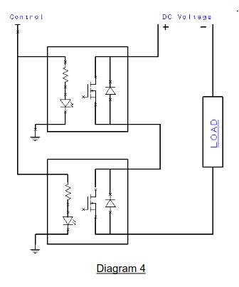
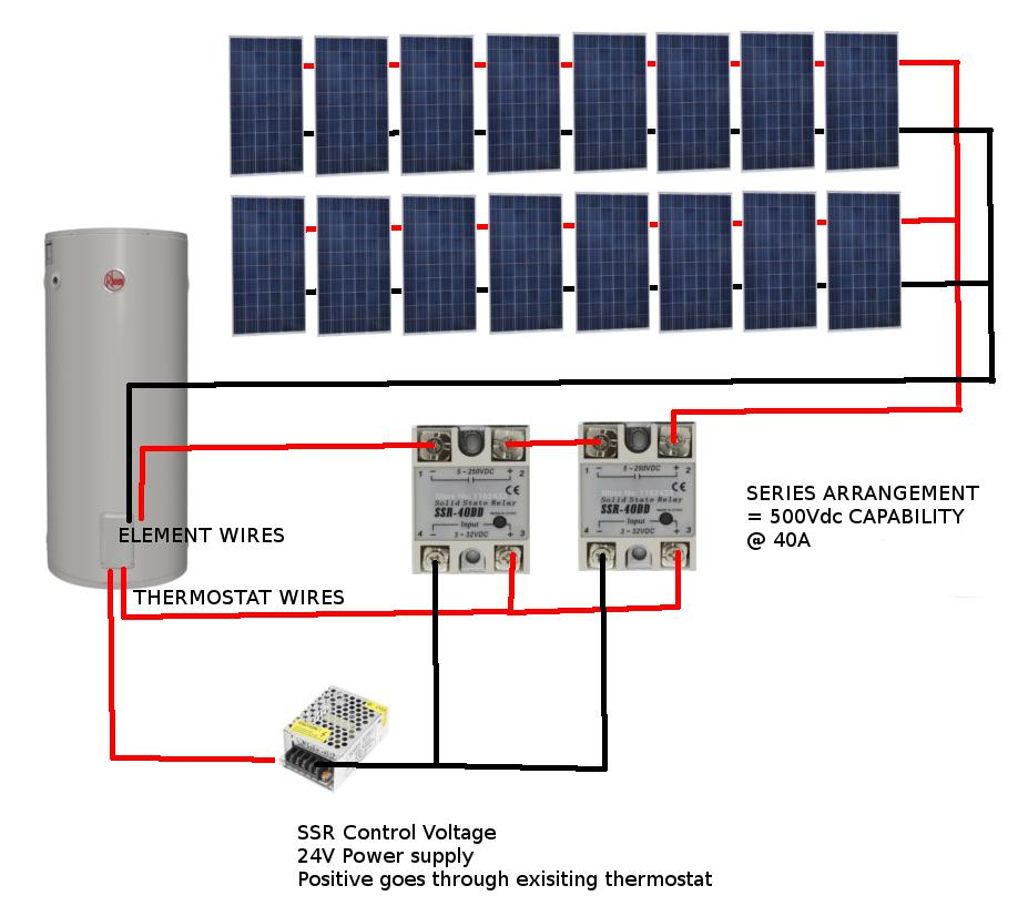
You will need 2 DC SOLID STATE RELAYS (SSR). The trick here is to run them in SERIES to get us a higher line voltage rating which takes into consideration the OPEN CIRCUIT voltage of the SOLAR array.
Each SSR can handle 250VDC @ 40A. When they are put in series, the setup can handle 500VDC @ 40A. Each SSR will still produce the same heat as in a single configuration.
Note the polarity of each solid state relay. The idea is, Solar POS goes to POS of relay 1, NEG of relay 1 goes to POS of relay 2, NEG of relay 2 goes to SOLAR NEG. The load is the heating element terminals.
You can use 12V, 24V or whatever voltage for the control system as long as its over 3Vdc and under 32Vdc.
I would recommend 24Vdc and use the power supply running off the wall. The issue with that is if your grid power goes down you wont have hot water either.
OPTIONAL CONTROL POWER
I have been toying with the idea of using wide input range mains LED Drivers as high voltage DC input power supplies. You can see that these drivers use rectification to create DC from mains to drive the SMPS circuitry.
So if you feed it the solar voltage, then it will create 12V/24V from it.
The unit I chose had: AC 85V to 265V to DC 20-38V 600mA.
With that in mind, 85*1.414 = 120Vdc and 265*1.414 = 374Vdc.
So this power supply can handle a DIRECT DC input of 120Vdc to 374Vdc.
Perfect.
Yet another SIMPLER Control Power Source
An even simpler power source for the control voltage would be to use a voltage divider arrangement.
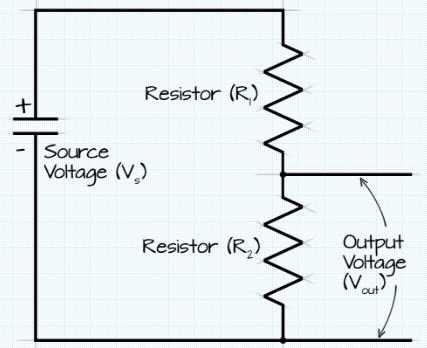
Basically, Vout = Vs x R2 / (R1+R2)
Vout would go to drive the control inputs of the SSRs.
So for a maximum input Vs of 500Vdc and R1 = 200Kohm and R2= 10kohm, Vout/Vcontrol = 23.81Vdc.
As a comparision, the minimum operating solar voltage would be 69.3Vdc to give us a control voltage of 3.3Vdc to turn on the Solid State Relays.
May I suggest you use 1/4W or 1W resistors in this application. A circuit like this only works because the SSRs have a wide input voltage of 3V to 32Vdc to operate.
Additionally I suggest you use a WYE configuration as shown below to further current limit the supply to the SSRs.

Where X is connected to Solar POS, Y to Solar NEG, Z to the SSR Control POS Side and the Solar NEG connected to the SSR Control Neg.
Use R1 = 200kohm, R2=10kohm, R3= 100ohm
Connections
Follow the diagram below.
Parts Required For this Project
It would help me out greatly if you use the links below to purchase the parts. There is no additional cost to you. In fact I’ve ordered from these suppliers with much success so consider these sellers audited.
| Part | Description | Quantity Required | Purchase Link |
| 250VDC 40A SOLID STATE RELAYS | You will require two of these for the project | 2 | http://ali.pub/2lspc4 |
| SSR 40A Heasinks | Needed for this project to safely dissipate the heat loads | 2 | http://ali.pub/2lspl9 |
| 12VDC Plug Pack | Use this option if you want to power the control circuit using 12VDC | 1 | http://ali.pub/2lsznp |
| 24VDC Plug Pack | Use this option if you want to power the control circuit using 24V | 1 | http://ali.pub/2lt02o |
| 85-265Vac LED Driver | Use this option if you want to use solar power to drive the control circuit. See above to work out how to use it. | 1 | http://ali.pub/2lt04t |


