ESP32 ADC to measure below 100mV

Just a short post to cover how to measure voltages below 100mV. I recently was trying to use a HP Common Slot PSU to drive a electrolysing unit. Instead of using my own shunt I decided to use Pin 34 IMONITOR to measure the current output.

What i found was that for currents under 5A, I was getting no reading on the ADC. That is because at 11db Attenuation at 12bits, the minimum measurable voltage is 0.1V or 100mV.

Instead of going down the path of using op-amps. I decided to modify my prototype pcb by changing the tradiional voltage divider input into the following.

Datasheets say (from Murata) that the IMONITOR pin puts out 60.15mV/Amp. For the 60.15mV/Amp the swing would be 0 to 3.9V.

So for 10mV of input the ADC would read 1.216V which is well within the linear range of the ADC. At 12bit resolution thats easily doable.

I found with my 750W HP supply, it was 30.15mV/Amp. So for this 62.5A supply, this would mean a swing from 0V to 1.88V.

The ADC would see 1.101V for 10mV of input.

Note that the leftmost resistor can be adjusted to allow a wide range of inputs offset against the 10K/10K/5V divider.

Hope this helps someone out there …


DIY Keg Floating Dip Tube Mk3

Move over Mk2

In Mk2 version, the float was signficantly simplified however setting it up was difficult and I started to move away from the idea of using Oetiker clamps inside the keg (is it safe?)

MK3 would have to be the simplest design yet!

Mk3 Simple Float

Mk3 works as follows

  1. The same float from Mk1 & Mk2
  2. The same replacement gas diptube OR cut down your existing liquid diptube. However now you need another piece for the end of hose
  3. The same length of silicone tubing as Mk1 & Mk2 60cm
  4. A length of 316L TIG 1.6mm wire is bent to capture the flared end of the diptube and is anchored freely onto the float!

Now the float has an indentation/dimple in the side that is HEAVIER is pretty much irrelevant! You dont needs washers clamps etc. Just some hose, a float and some wire!

Parts Required

Stainless Steel Float https://alii.pub/6j2oin

Food grade Silicone hose (use 7×10) https://alii.pub/6j2o4u

The list above will probably contain more parts than you need to make one float. ..

UPDATE: I published this a long time ago. If you want a turnkey solution you can use this. Its a stainless steel ball with the hose and diptube as a kit.

https://alii.pub/6j2ofj

Results

A thing of beauty!

Right down to the very end!

Feedback

I would appreciate some feedback on this new design if you decide to build mk3…

I must say testing it was a pleasure…no more spurts and carry ons…straight clean pour to the end!


F-TPMS Fermentation Monitoring Part 1

About 2 months ago I saw Andreas Speiss talking about using TPMS sensors for monitoring his bottle carbonation. He was having to fabricate a cap that could accomodate the sensor. It got me thinking. Why can’t I just use the outboard sensor types with a valve stem and call it day?

So I decided to add some off the shelf EXTERNAL type TPMS sensors to my brewing kegs. I call it Fermentation Temperature Pressure Monitoring System or FTPMS. Yes…I like acronyms.

Some background if you require it….A TPMS (Tyre Pressure Monitoring System) uses wireless temperature and pressure sensors on each valve stem to monitor and warn of out of bounds conditions namely over/under-pressure, over-temperature. They report back to a central controller with a display for temperature and pressure.

These measurements are highly useful in pressure fermentation or Grünschlauchen, not so much plastic fermenter type setup…

I bought the set of four because you get the display and receiver unit which I will hack in Part 2 to allow you to run more than 4 sensors.

I used an off the shelf tyre valve stem that was designed to fit to high quality alloy wheels rather than the push in rubber type.

These are made out of stainless steel. All you have to do is drill a 8mm diameter hole in the top of the keg lid and then fit this valve assembly.

Installation

I used a 90 degree brass motorcycle valve stem for mine. Similar to the one below:

The Schrader thread was a bit shite so I had to clean it up for the TPMS sensor to fit nicely. My advice is to use the stainless steel stem shown in this post.

The Result

Thats the Rear Left sensor fitted to Fermentation Keg 1. I have two fermentation kegs so I used R.L and R.R.

On the screen it is showing the telemetry:

As you can see the screen reports back the temperatures in C and the pressures in Bar.

Parts Required

You can convert up to 4 kegs with 1 kit.

4 sensor TPMS EXTERNAL SENSORS with Receiver

4X schrader valve stems

In part 2, I will be finding a way to run more than 4 sensors using a custom made Arduino based 433MHz receiver….

I2C/IIC longer cable runs without extenders

Recently I was building some custom boards which had an 0.96″ OLED display that was remotely mounted. In my prototyping I noticed no ill effects from extending the 4 core cable to the OLED display.

The wiring comprised of GND, 3.3V, SCL and SDA signals. I had 4.7K pullups at the board side.

Then came the issue when I had replicate across the production units with the cables at 2.2m each.

I was perplexed since I had a working example at 2m.

The only difference was the prototype used 4 core screened audio cable (individual screens) vs the production version of single screened UTP.

Turns out, CAT6 is a poor choice for I2C even at lengths of a metre or so. Even with the following configuration:

  • SDA on Orange
  • GND on Orange/White
  • SCL on Brown
  • GND on Brown/White
  • 3.3V on Green
  • GND on Green/White
  • 3.3V on Blue
  • GND on Blue/White

I tried varying the clock speed from 700KHz to 400KHz to 100KHz to 10KHz  and even 100Hz…no such luck.

I even tried adding a separate 3.3V power supply and additional pull ups at the OLED panel. No luck.

Turns out the solution was under my nose all along. The 4 core screened audio cable. Specifically from Jaycar, WB-1510, works flawlessly at lengths up to 3m (that I have tested). It could work with even longer lengths! Just make sure you ground all the screens at the board end to earth/chassis.

Hope this helps someone out there that is having issues with I2C beyond a metre….

DIY Keg Floating Dip Tube Mk2

Move over Mk1

In Mk1 version, there was a filter. I got feedback that this was causing grief when it got blocked. Additionally the build cost was on par with the off the shelf Fermzilla float. Well, we can’t have a situation where DIY cost more in parts than the commercially available item!

Mk2 Simpler Float

Mk2 works as follows

  1. The same float from Mk1
  2. The same replacement gas diptube OR cut down your existing liquid diptube
  3. The same length of silicone tubing as Mk1
  4. Except now, the float is held in place by two 316L 8mm flat washers, held in place by 2 Oetiker clamps.
  5. Note, the Oetiker clamps are push fit on this 8mm tube since they are 7mm. DO NOT CRIMP the clamps as you will not be able to dismantle and clean the float.

Notice that the float has an indentation/dimple in the side that is HEAVIER. You need to face this side to the bottom. If your float doesn’t have an indentation, you can find the heavier side by placing the bare float in a jug of water.

This is the bottom side of the float. Leave about an inch of tube overhang.

This the top side of the float. Don’t make the fit tight as you want the float to rotate freely on the tubing. Again DO NOT CRIMP the Oetiker clamps.  In the photos it is apparent that I did clamp mine because they were oversized. I used 9.5mm Oetikers for the prototype as that is what I had on hand).

As you can see below, the float  sits with the diptube under the water level.

You can fine-tune the float by adding more washers to the bottom side if your float does not behave properly.

Parts Required

Stainless Steel Float http://ali.pub/229u9j

Food grade Silicone Tube 10mm OD 7mm ID http://ali.pub/229umy

8mm Keg Diptube Short/Gas http://ali.pub/229vui

316L Washers (need 2) http://ali.pub/3ru9v6

7-9mm Oetiker Clamps (need 2) http://ali.pub/3ru9r3

Note, the clamps are not crimped. The only reason you would crimp them slightly is to get a tight (interference) fit on the silicone tube. This will allow you to adjust / fine tune and more importantly clean your diptube float assembly.

The list above will probably contain more parts than you need to make one float. ..

Feedback

I would appreciate some feedback on this new design if you decide to build mk2…

UPDATE 18.10

Mk3 is ready and working better than ever and way cheaper!

http://think.gusius.com/diy-keg-floating-dip-tube-mk3/

Building a low-cost PCB Assembly Line Part I

Organic Prototyping with low cost modules

I have been a maker pretty much all my life. PCB fabrication has always interested me from constructing prototypes on vero board to toner transfers onto dual sided FR4 board.

As time went on, the through hole components gave way to the SMT parts that initially were OK to install by hand (eg 1206 and to some extent 0603).

My progression to 0402 parts and jittery flair for coffee in the morning has made it quite laborious to work with so I decided just like many makers out there to invest in a PCB assembly line.

Note, in this day and age with the likes of JLCPcb (AKA Shenzen JLC Electronics Co Ltd AKA JiaLiChuang (HongKong) Co Ltd), PCB fabrication at home is now relegated to “doing art” and no longer a practical nor time economical  activity. So we will just focus on assembling fabricated PCBs using a commercially made Stencil.

The Process

Well this one is real simple. We will take a commercial assembly process and reduce it down we get the following process.

We will need a Solder Paste Printer, a pick and place machine and a reflow oven.

Solder Paste Printer

After much research and my own experiences setting up stencil jigs, I want a printer that allows fine scale control over the levelness of the pcb while “squeegeeing”.

Enter the 3040 Printer.

Features:

  • Work table size: 300*400mm (Pretty much standard low cost stencil from JLCPcb)
  • Print size:  250*400mm
  • Max net frame size:  370*470mm
  • Thickness of the substrates:  0-80mm
  • Workbench adjustment volume:  10mm Horizontal Angle adjustment
  • Printing platform height:  220mm
  • Claimed Repeated accuracy:  +-0.01mm
  • Locate mode: Benchmark or hole shape Dimension 540*370*350 mm
  • Weight: 25Kg

Pick & Place Machine

I want something that has some good reviews already and the thumbs up from fellow makers. I don’t need something with a million feeders but I do want something with around 20-30 feeders, a separate IC tray area and possibly tubed IC feeding capability.

On a budget the following machine seems to be the way to go. The Charmhigh CHMT48VA.

Features:

  • Dimensions L 960mm*W 705mm*H 335mm
  • PCB Area 10*10~355*355mm <– More than enough for the stencil print size
  • XY Axis travel 400*460mm
  • Z axis move range 15mm
  • Pick and Place heads 2pcs
  • Mounting Speed:
    • With vision 3000~4000cph
    • Without vision 6000cph-7000cph
  • Working Precision ±0.025mm
  • Reels/Feeders/Stacks/Trays:
    • 8mm=22 stack
    • 12mm=4 stack
    • 16mm=2 stack
    • 24mm=1 stack
    • Front IC=14 stack
    • User-defined IC tray
  • Vacuum pump 2pcs in-built
  • Vision system Up view and down view dual cameras
  • Computer system inside Linux system inside,
  • CSV file By Protel 99SE ; Altium Designer and Eagle
  • Touch screen 7’’ (15.6cm*9.3cm) industry touch screen
  • Support packages 0402,0603,0805,1206,1210,3528,5050, SO-16,SOT-23,SOT-89,TO-252,SOP,QFN, LQFP….different kinds of IC (max size 22*22mm)

Reflow Oven

Again, lots of people out there with reviews on ovens. The Puhui T962 series seems to be bagged a lot but there are some fixes to get it working “properly”

I am going to go with the latest iteration the T962C and see how it goes. It has had a good review from the Superhouse guy (Andrew)…

Prediction: I have a feeling I’m going to have to build an oven myself….

My Purchases

These affiliate links help me in a small way at no extra cost to you. I have personally bought from these sellers and can verify they delivered the goods.

CHMT48VA + Vibration Feeder (tube feeder)

The pick and place machine with 29 feeders and a tube vibration feeder for ICs in tubes.

3040 Stencil Printer / Manual Solder Paste Screening Machine

This stencil printer is much better than the cheaper ones as it allows you to prop the board if its thin and has variation in flatness

Once these purchases arrive I will review them in Part II…

Φ80MM 6V 2W Round Style Polycrystalline Solar Panel FAIL


6V 2W bargain panel?

I have been searching for a solar panel to power some of my standalone ESP8266/32 projects and I have evaluated a bunch of panels. This particular panel got my attention because of its clamied power output and efficiency.

This is what the manufacturer/seller claims:

Specifications

Maximum power: 2W
Working current: 0.35A
Operating Voltage: 6V
System current: 6V
Open circuit voltage: 6.6V
Short circuit current: 350A
Parallel resistance: 0(ohm)
Series resistance: 1(ohm)
Conversion efficiency: 18(%)

Of course the short circuit voltage is wrongly provided at 350A. Surely its 350mA?

Test & Application

I did the tests for open circuit voltage and short circuit current using a Fluke 87 Multimeter.

Sunlight was at 30degree incident for Voc test. Came in at over 6V.

However disappointingly, the first short circuit test came in at a mere 64.9mA!

Second test with panel facing the sun directly came in at 73.9mA.

As you can see its nowhere near the claimed 350mA.

Very disappointed….

Verdict

Poor performance for size. Avoid.

Reference to panel

http://ali.pub/331p8v


DIY 54Vdc 30A Battery Bulk Charger – Mk 2

Look Ma no fans!

In Mk1, I used a 48V UPS. In Mk2 I use two 24V APC UPS transformers in series. Basically I take the two identical transformers and double the voltage output for the same current. This gives my power supply a 3000VA capacity!

The donor housing for this project was a dead Growatt 1500W Grid Tie Inverter. I did this to allow for a fanless IP54 rated wall mount unit.

Yes you read right. Aside from the 50Hz hum, there is no annoying fan sound.

Design

The concept here is basically we run this unit off  a generator which kicks in when the battery bank (for my off grid setup) drops below 46V. This supply/charger tied to the battery bank and can be used to feed the inverters and also top up the battery bank as required. The CC and CV functionality works in a safe manner to ensure we don’t damage the battery bank.

Mk2 design doesnt change much from mk1 which can be seen in my previous blog link http://think.gusius.com/diy-48v-dc-30amp-bulk-battery-charger-mk1/

For completeness the block diagram is shown below:

This time the transformer is in two parts.

Also we are using a better volt/ammeter which has a wide input range and does not require an external buck converter.

The Transformers

I stripped down the APC 3000VA UPS transformers which were Class H rated! There were two of them with series secondaries to work with 48V.

Wiring the primaries in parallel and the secondaries in series gave me around 30Vac open circuit.

The Enclosure

I was given a Growatt 1500W Sungold grid tie inverter that had apparently stopped working.

The good thing about stripping old broken grid tie inverters is you get some nice high voltage inductors, filters, relays, connectors etc.

Building it

The unit was stripped bare ready for use. Basically everything removed. The power filter side was bandsawed out to use as an input filter for this power supply.

The DC DC converter was stripped of its original heatsink and fan and then fitted directly to the enclosure’s massive heatsink.

Everything fit nicely.

Wiring It

Wiring is relatively simple. Just making sure you meet all the wire ratings and size for the current and voltage requirements in each stage.

The Anderson SB50 on the left goes to your battery bank. The two blue connectors are used to remote turn the unit on and off using 12Vdc. The 3 terminal block on the right is the AC input from the generator or mains.

I used my Midnite Charge controller AUX 1 output to drive the unit ON/OFF based on Low Voltage Detect of 46V.

Summary

Having a noiseless, IP67 (or even IP54) rated battery charger as a backup unit for my offgrid setup is quite the holy grail.

Update: What do those trimpots do?

There are three trimpots on the converter. The diagram below shows what they do…

Parts For the Project

An old grid tie inverter to suit [QTY 1 required]

6.5-100Vdc LCD Combo Meter + 100A shunt [QTY 1 required]

2pcs 50A 1000V Diode Bridge Rectifier Modules [QTY 2 required, four in total]

1800W 40A DC DC converter module CC CV [QTY 2 required]

Anderson SB50 Plug

3pcs 10000uF 80V DC smoothing capacitors [QTY 1, 3 pieces required]

DIY 48Vdc 30A Bulk charger – Mk 1


Being off-grid means energy freedom for me. However freedom from the grid also means attachment to the whims of nature and the waxing and waning cycles of light from the sun, intermittent wind.

There are days when my energy system storage gets low enough to warrant some stress about running out of power. The thing I found, there aren’t a lot of low cost options to bulk charging a DC bank of batteries properly and safely.

I can’t stress how important it is to have CC and CV capability otherwise you will most likely fry your batteries without any form of external voltage and current management!

Design

I decided to look into a cheap (ish) way building a bulk charger for my 2600Ah 48V battery bank. I settled upon the idea of using a low frequency transformer linear power supply from mains then passing that into some sort of CV/CC DC DC boost converter.

I came up with the following topology:

The idea would be to salvage a low frequency transformer from a high capacity UPS, rectify the low voltage output then feed it into the boost converter set to 54Vdc at 30A.

Self deprecation (sort of)

I know you’re thinking why go through all this trouble when you can just plug in the UPS into wall socket and break out the DC leads and plug it straight into the battery bank.

Well here is my list of cons:

  • Non-resettable overcurrent protection – basically your bank will be much larger than the original battery bank in the UPS which means that you may exceed the current capability for charging of the UPS
  • The charge rate isnt fantastic- I’ve noticed that the UPS in charger mode is actually a pretty slow charger for larger banks
  • When power goes off it starts the inverter inside….which even at no load wastes power! I suppose you could unplug it or turn it off…I wanted a handsfree solution
  • All those fans inside would waste a lot of power (the UPS I used had two fans that ran all the time!)

Boost Converter Module

A total monster unit…all pre-assembled for you!

Specifications:

  • Output: 1800W
  • Input voltage range:  10V-60V
  • Output voltage range:  12V-90V
  • Input current: 40A
  • Output current: 22A (I was able to push to 30A at 54V out)
  • Dynamic response speed: load current change 5% (300us)
  • Conversion efficiency:
    • 48V to 60V 8A (98.1%)
    • 48V to 72V 8A (98.1%)
    • 48V to 84V 8A (97.6%)
    • 48V to 54V 30A (Efficiency TBA <– I will calculate and post soon)
  • Load regulation: 10% to 50% load ((72V output))
  • Temperature coefficient: 50% load
  • Ripple & Noise: 20MHz Bandwidth (48V-72V 4A) 100mVp-p
  • Switching frequency: VIN=48V VO=72V 4A (110khz)
  • No-load current: VIN=48V VO=72V (18mA)
  • Output short circuit protection: YES
  • Input reverse protection: YES
  • Working temperature: -20 65°C
  • Temperature rise during work: 48V to 60V 5A (45°C)
  • Over temperature protection: (60°C)

Modifications required:

  • Breakout the current setting pot to an external panel mounted job. The CC pot on my module was a W502 or 5Kohm multi turn
  • Remove the onboard fuses and replace with copper links (ONLY if you are running the external breaker)


Putting it together

Basically you find a UPS that runs on your country’s mains voltage (in my case thats 230Vac) or the generator’s output voltage and uses a 48V dc battery bank. The idea is you can use any external source of mains AC to drive this.

You strip out the PCB and control/display board but perhaps leaving a portion of the AC EMI filter circuitry (completely) optional.

Rewire the transformer so that the mains comes in and directly feeds the high voltage side of the transformer.

You then wire the low voltage secondary to a pair of diode bridge rectifier modules in parallel to give you some redundancy.

The “un-smoothed” rectified DC is fed into a bank of 3 x 10000uF capacitors rated to 63V or more. I suggest you go with 80V to be safe.

This is then fed into the input of the DC DC boost converter.

The boost converter is modified to have its on-board multi-turn constant current pot broken out into a panel mounted version. This then allows you to set the output current.

The output of the converter is then connected through the DC breaker, then the current shunt and then to the 50A Anderson connector at the back.

Note the voltage should be preset inside and I don’t recommend you break that out in case someone decided to crank out 90V and destroy your batteries and possibly your charger.

The “VOLTAMMETER”

Cut the front panel of the UPS and fit the voltmeter/ammeter combo. The unit needs 12-30V to work so use the buck XL7015 unit that can handle up to 80V input (see parts list). Wire the input of this converter to the DC smoothing bank and not the boost converter (why use up those precious watts from the converter?).

Wiring Guide

Below is just a rough wiring/schematic for the project. I leave it to you as an experienced engineer/technician/sparky to deal with the detail via your towering intellect and aeons of experience 🙂

Settings

Set the voltage output to between 54 and 56 volts depending on your battery bank type. Set the current to a few amps first to test things out.

UPDATE: I will be developing a MK2 version in which I will be using two of the modules examining the mosfets and current shunt used on the board to maximise the output current capability. I also plan to simplify the design.

Parts I used in this project

Below are a list of items I used in the project. These are affiliate links with Aliexpress that provide benefit to me without any extra cost to you. I appreciate your support of my work.

Compaq UPS 2200XR. <– Find a decent secondhand UPS with at least 1800VA 48V rating, you will find the transformer inside.

1800W 40A DC DC converter module CC CV

0-100V, 0-50A combination voltmeter/ammeter including 50A shunt

XL7015 v2: 5-80V to 12V Buck converter module

2x Anderson 50A red connectors

2P DC breaker 40A C curve OR

2P DC breaker 32A C curve OR

1P DC breaker 20A C curve

5K Multi-turn pot panel mount

Knob for the multiturn pot

2pcs 50A 1000V Diode Bridge Rectifier Modules

3pcs 10000uF 80V DC smoothing capacitors

AC Hot Water Conversion to Solar DC

Grid Tied Solar Power

As the price of electricity soars in Australia, solar power starts to become more financially logical pathway with much less total cost of ownership times (TCO).

We can go down the route of getting a grid tied system using the STCs available to our homes but the usual topology is a DC to AC coupled system via a grid tie inverter. The power is fed back through the meter and you receive a modest return on your investment. If you were to then run your hot water heater you would still be behind…
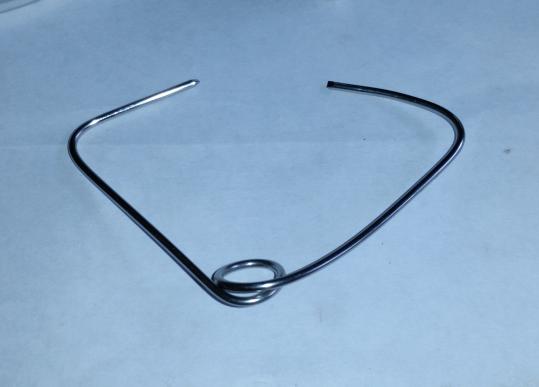
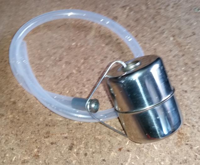
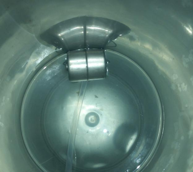
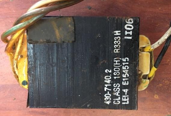
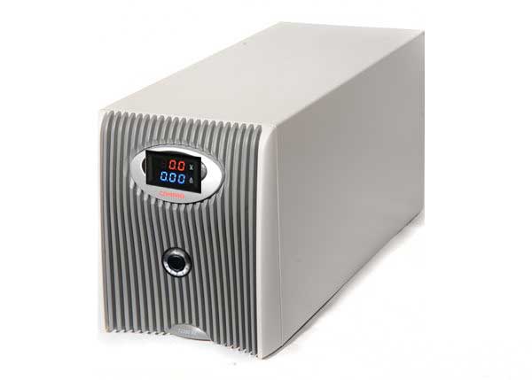
Rheem 250L Tank

The unit I have is a Rheem 250L. Specs are:
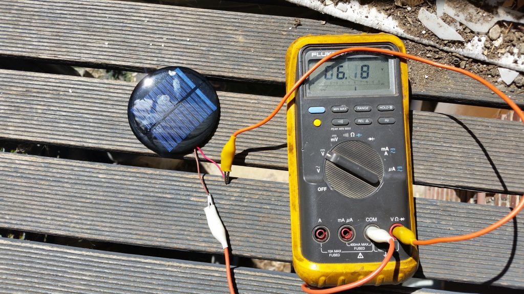
Direct Current

A hot water heater is generally a resistive element (almost ideal resistance) rated to 240Vac (for a 3600W element) use. This translates to an operating current of 15A.

The beauty of a resistance is that it does not really matter if the voltage is AC or DC. A suitable way of running the heater directly off solar is to wire the panels in way such that the Vmp and Imp match closely the operating voltage, current and resistance of the element.

In my case, I have a Rheem Model 111250 250L single element heater. It has a 3600W element. The cold DC resistance of the element measures at 15.3Ω. The expected current required is 15A.

The panels I got for this exercise are Trinasolar TSM-250 PC/PA05A.

Specs:

  • Pmp 250W
  • Vmp 30.5V
  • Imp 8.2A
  • Voc 37.8V
  • Imp 8.9A

We will be running the hot water heat at around 220Vdc to 250Vdc. To achieve this, we need 8 panels in series. 8 panels in series gives us a Vmp of 244Vdc (perfect!). The Imp per string will be 8.2A. If we parallel up 2 strings we get Imp of 16.4A…damn good. In fact even 8.2A is plenty if you are using as a way of preheating water.

Maximum Power Point Resistance

So whats our array’s Rmp then? Rmp = 244 / 16.4 = 14.87Ω

Damn close to the cold DC resistance of the element. Generally the element’s resistance goes UP as it heats up..so we move further away from the ideal 14.87Ω resistance.

This method is OK when the sun is shining and panels are pushed into maximum power point with the (pretty much) fixed resistance of the hot water element.

Easy right? Well not quite….the first issue is, the hot water heater’s thermostat contacts are designed to handle AC loads only….so we have to use a contactor/SSR to switch the solar panels in and out.

Problem is high voltage DC solid state relays are rare and if they do exists they cost a LOT. Getting a contactor to switch out over 220Vdc cheaply is asking for a lot.

You could use a MOSFET or IGBT to do the switching where the gate is driven by a circuit triggered by a lower voltage driven through the existing thermostat. Seed for another project.

The Design

Basically if you follow the design below I’ve come up with, you will not be violating any laws to do with hot water systems in Australia. Namely because:

  1. You will be maintaining the PTR valve, Expansion valve and other safety valves as per original
  2. You will not be replacing/bypassing the ORIGINAL temperature driven thermostat.
  3. You will not be exceeding the DC/AC voltages of the system
  4. This will run independently to your grid power (it is technically OFF THE GRID)
THE IDEA

The plan is to install the solar panels in 2P x 8S configuration (8 panels in series then 2 strings in parallel). Bring that to where the HW unit is.

Then create a DC secondary thermostat contact point using the original thermostat as the trigger mechanism

CONTROL/SWITCHING

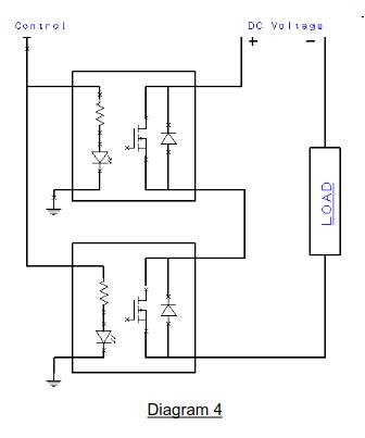
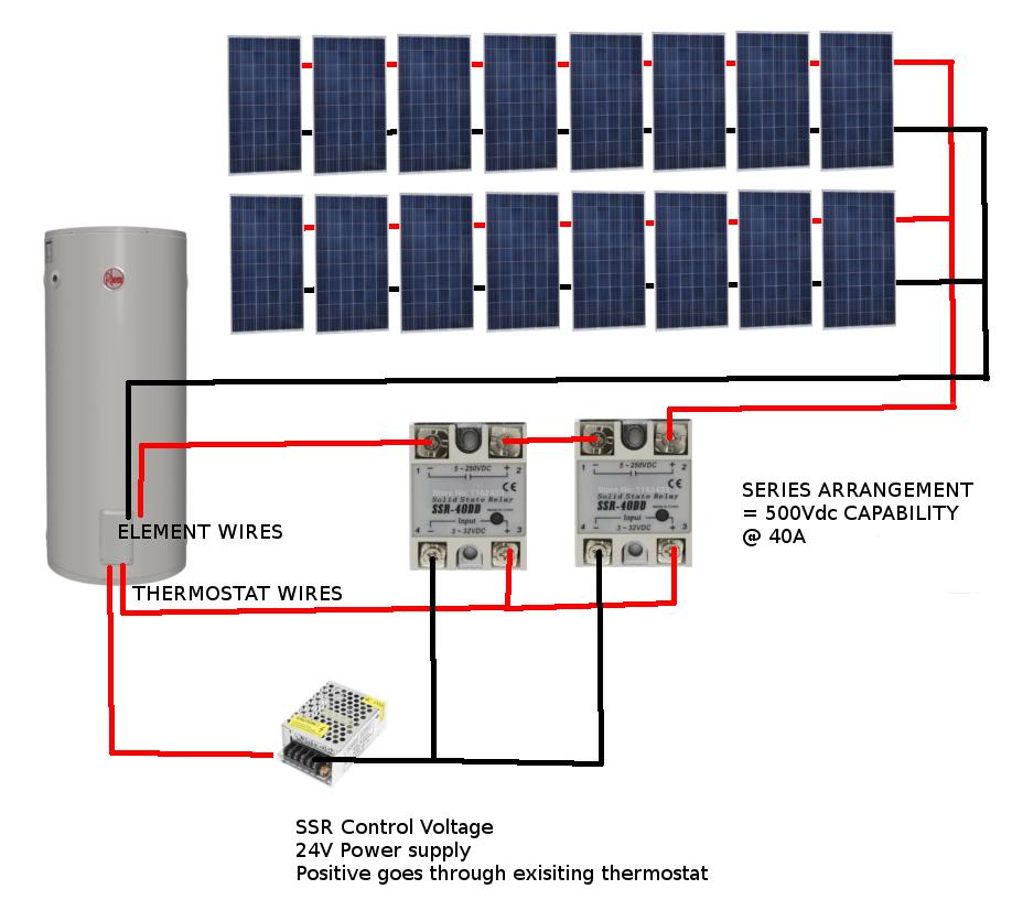
You will need 2 DC SOLID STATE RELAYS (SSR). The trick here is to run them in SERIES to get us a higher line voltage rating which takes into consideration the OPEN CIRCUIT voltage of the SOLAR array.

Each SSR can handle 250VDC @ 40A. When they are put in series, the setup can handle 500VDC @ 40A. Each SSR will still produce the same heat as in a single configuration.

Note the polarity of each solid state relay. The idea is, Solar POS  goes to POS of relay 1, NEG of relay 1 goes to POS of relay 2, NEG of relay 2 goes to SOLAR NEG. The load is the heating element terminals.

You can use 12V, 24V or whatever voltage for the control system as long as its over 3Vdc and under 32Vdc.

I would recommend 24Vdc and use the power supply running off the wall. The issue with that is if your grid power goes down you wont have hot water either.

OPTIONAL CONTROL POWER

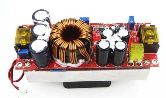
I have been toying with the idea of using wide input range mains LED Drivers as high voltage DC input power supplies. You can see that these drivers use rectification to create DC from mains to drive the SMPS circuitry.

So if you feed it the solar voltage, then it will create 12V/24V from it.

The unit I chose had: AC 85V to 265V to DC 20-38V 600mA.

With that in mind, 85*1.414 = 120Vdc and 265*1.414 = 374Vdc.

So this power supply can handle a DIRECT DC input of 120Vdc to 374Vdc.

Perfect.

Yet another SIMPLER Control Power Source


An even simpler power source for the control voltage would be to use a voltage divider arrangement.

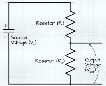
Basically, Vout = Vs x R2 / (R1+R2)

Vout would go to drive the control inputs of the SSRs.

So for a maximum input Vs of 500Vdc and R1 = 200Kohm and R2= 10kohm, Vout/Vcontrol = 23.81Vdc.

As a comparision, the minimum operating solar voltage would be 69.3Vdc to give us a control voltage of 3.3Vdc to turn on the Solid State Relays.

May I suggest you use 1/4W or 1W resistors in this application. A circuit like this only works because the SSRs have a wide input voltage of 3V to 32Vdc to operate.

Additionally I suggest you use a WYE configuration as shown below to further current limit the supply to the SSRs.

Where X is connected to Solar POS, Y to Solar NEG, Z to the SSR Control POS Side and the Solar NEG connected to the SSR Control Neg.

Use R1 = 200kohm, R2=10kohm, R3= 100ohm

Connections

Follow the diagram below.


Parts Required For this Project

It would help me out greatly if you use the links below to purchase the parts. There is no additional cost to you. In fact I’ve ordered from these suppliers with much success so consider these sellers audited.

PartDescriptionQuantity RequiredPurchase Link
250VDC 40A SOLID STATE RELAYSYou will require two of these for the project2http://ali.pub/2lspc4
SSR 40A HeasinksNeeded for this project to safely dissipate the heat loads2http://ali.pub/2lspl9
12VDC Plug PackUse this option if you want to power the control circuit using 12VDC1http://ali.pub/2lsznp
24VDC Plug PackUse this option if you want to power the control circuit using 24V1http://ali.pub/2lt02o
85-265Vac LED DriverUse this option if you want to use solar power to drive the control circuit. See above to work out how to use it.1http://ali.pub/2lt04t